How to install an angular contact bearing. Great encyclopedia of oil and gas
After a preliminary design of the shaft and associated gear parts, rolling bearings are selected. The design and quality of the supports are determined by the type of bearings, their installation pattern and the method of fastening in the housing and on the shaft. This, in turn, depends on the operating conditions - the magnitude, direction and nature of the load, the length and rigidity of the shaft, the type of lubricant, protection from contamination; accuracy of manufacturing of parts and housing (alignment of holes), quality of installation, need for adjustment and dismantling of bearings; resource (service life) of bearings before replacement; efficiency, cost of bearings and supports in general. All this allows you to select the type of bearings and design the supports.
Selection of bearing type. Bearings are standard products. When designing machines and mechanisms, they are selected from catalog tables (see Tables P.5...P.15).
When choosing a bearing size for a given shaft diameter d and operating conditions should be taken into account: the magnitude, direction and nature of the acting load; shaft rotation speed; required work resource per hour; special requirements depending on the design of the unit or machine and its operating conditions; bearing cost.
In table 8.1 shows sketches of bearings most often used in mechanical engineering practice.
In accordance with established practice in the design and operation of machines, the type of bearings and their installation scheme are selected according to the following recommendations.
For shaft supports of cylindrical spur and helical gears For gearboxes, radial ball bearings are most often used (Table 8.1, clause 1). Light series bearings are initially prescribed. If the size of the ball bearings is excessively large, tapered roller bearings are used as supports for the shafts of cylindrical wheels (Table 8.1, clause 4).
Table 8.1. Rolling bearings of the main types.
Table 8.2. Pre-selection of bearings

Table 8.3. Approximate dependences of the dimensions of the internal structurebearings for sketching and drawings
![]()
Radial ball bearings are characterized by low axial rigidity. Therefore, in power transmissions, tapered roller bearings are used to support the shafts of bevel and worm wheels (Table 8.1, clause 4). Initially choose a light series.
For bevel gear shaft supports tapered roller bearings are adopted for the same reasons. At high gear shaft speed (P>1500 min -1) take a light series.
Worm supports in power worm gears are loaded with significant axial forces. Therefore, tapered roller bearings are mainly used as supports for the worm shaft. For long-term continuous operation of a worm gear, in order to reduce heat generation, angular contact ball bearings are also used (Table 8.1,
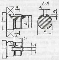
For floating shaft supports(worms at a distance between supports l> 200 mm, herringbone gears) radial ball bearings or with short cylindrical rollers are used on one side (floating support), and paired angular contact bearings on the other (see Fig. 8.1).
Bearing installation diagrams. In most cases, the shafts must be secured in supports against axial movements. Based on their ability to fix the axial position of the shaft, supports are divided into floating And fixing.
Floating supports allow axial movement of the shaft in any direction to compensate for its elongation (shortening) during temperature deformations. They perceive only radial force. Ball and roller radial bearings are used as floating supports, the types of which are shown in table. 8.1.
Fixing supports limit axial movement of the shaft in one or both directions. They perceive radial and axial forces. Ball and roller bearings are used as fixing supports, the types of which are shown in table. 8.1.
In the diagrams (Fig. 8.1, d, e, f) one support is fixing, the second- I'm swimmingshaya. The locking support limits the axial movement of the shaft in both directions. One or two bearings can be installed in the support, which are secured in the axial direction on both sides both on the shaft and in the housing. In a floating bearing, the inner ring of the bearing is fixed on both sides to the shaft, and the outer ring moves freely in the housing along the axis.
In this form (see Fig. 8.1, Where) a shaft with supports is a statically determinate system and can be represented in the form of a beam with one hinged-fixed and one hinged-movable supports.
Schemes (Fig. 8.1, Where) used at any distance between the shaft supports.
When choosing floating and fixing supports according to the diagrams (Fig. 8.1, d, e , f) take into account the recommendations:
The bearings of both supports should be loaded as evenly as possible, so if an axial force acts on the shaft, then the support loaded with a greater radial force is chosen as a floating one. In this case, the entire axial force is absorbed by the bearing, which is less loaded by the radial force.
In the absence of axial floating forces, a less loaded support is made in order to reduce the resistance to axial movement of the bearing and wear of the housing surface.
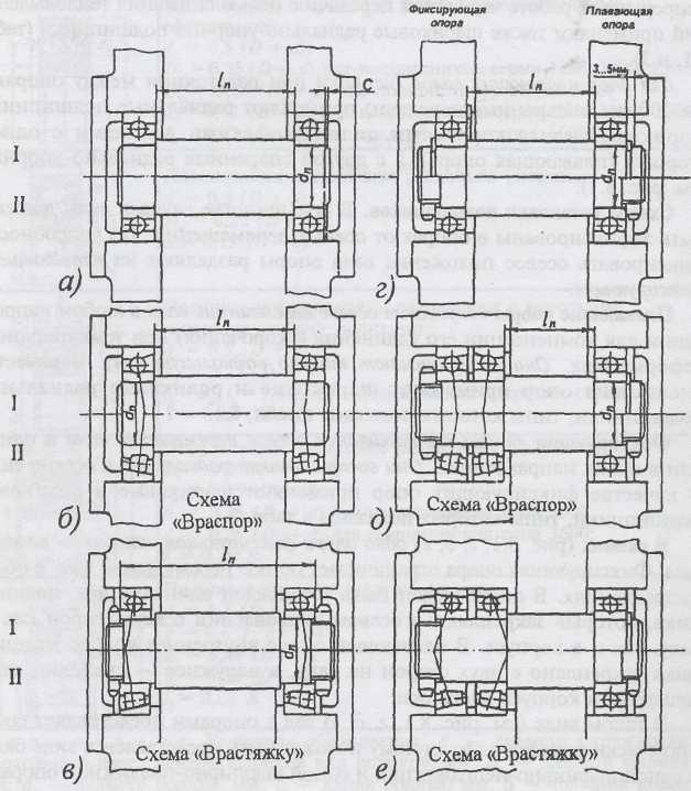
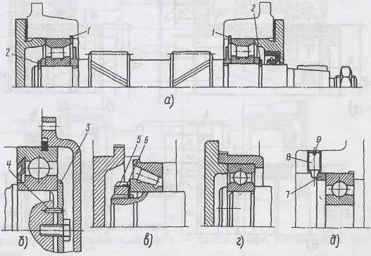
Rice. 8.1. Schematic diagrams of bearing installation and their fixation on shafts and housing
3. If the input (output) end of the shaft is connected to another shaft by a coupling, then the fixing one is a support near this end of the shaft.
IN diagrams(see Fig. 8.1, b, c) both supports are fixing, and eachthe support fixes the shaft in one direction. Bearings can be installed in the supports of these schemes: ball or roller radial (see Fig. 8.2, b and 8.2, G) and radial contact (see Fig. 8.2, V).
The specified schemes are used with certain distance restrictions 1 P between supports. This is due to changes in gaps V bearings during temperature deformations of shafts.
IN scheme(see Fig. 8.2, A), called bearing installation diagram "by surprise"(compressive stresses act from axial forces in the shaft sections between the supports), to prevent pinching of the rolling elements due to heating during operation, an axial clearance is provided A(not shown in figure). The gap size should be slightly greater than the expected thermal deformation of the bearings and shaft. It is known from experience what in units with radial ball bearings with 1 P ≤ 300 mm A= 0.2...0.5 mm. Required clearance A created during assembly using a set of thin metal spacers installed between the housing and the bearing cap.
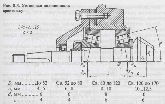
IN scheme(see Fig. 8.1, V), called bearing installation diagram "stretch" the possibility of pinching the rolling elements of bearings due to temperature deformations of the shaft is reduced, since in this scheme, as the shaft lengthens, the axial clearance in the bearings increases (see also Fig. 8.3). For this reason, the distance between the bearings may be slightly greater than in the standby scheme: 1 P ≤ (8..10) d n . Smaller values are for roller bearings, larger values are for ball angular contact bearings. For ball radial 1 P ≤ 12 d n .
Design of glasses. The bevel gear assembly with supports is usually enclosed in a glass, and it forms an independent assembly unit, which simplifies both the assembly technology and the regulation of the axial position of the gears.
The bearings are secured to the shafts against axial displacement (see Fig. 8.2, 8.3 and 8.5) using: end and lock washers, spline nuts, set screws, and spring thrust rings.
Radial clearance adjustment thrust bearings performed: with a set of gaskets, adjusting screws and special design techniques.
Depending on the arrangement of the bearings, the cups are designed according to one of the options shown in Fig. 8.4. When installing the glass into the housing with interference, the flange is made smaller, without holes for screws.
Glasses are usually made from cast iron grade SCh 15, less often from steel. Wall thickness  , diameter d
and number z
screws securing the glass to the body are taken depending on the diameter D
the holes of the cup for the bearing according to the following dependencies:
, diameter d
and number z
screws securing the glass to the body are taken depending on the diameter D
the holes of the cup for the bearing according to the following dependencies:
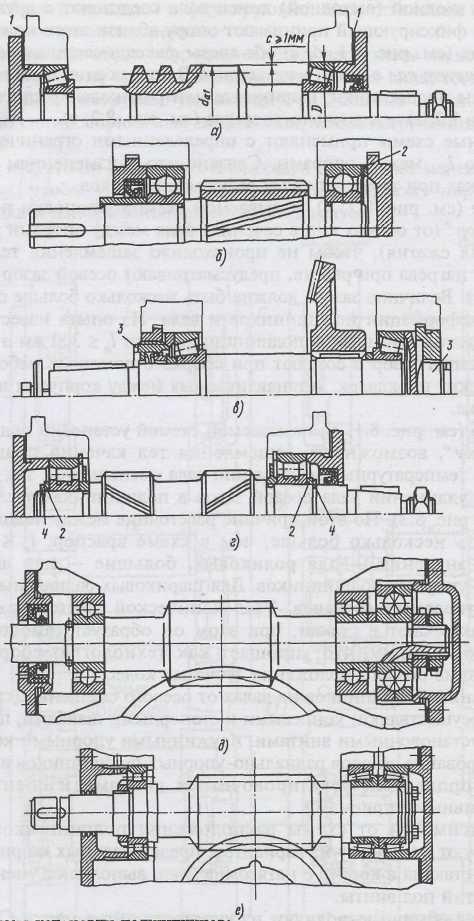
Rice. 8.2. Bearing installation diagrams:
a B C- by surprise; G- floating; d, f- the left support is floating, the right one is fixed
Question: For what purpose are parts 1...4 provided?
Thrust collar thickness 1 and flange thickness 2 (Fig. 8.4) are accepted 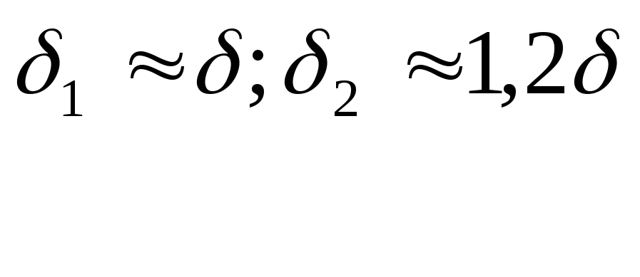
Height t
the thrust shoulder is assigned according to the same dependence as the height of the shaft shoulder h
(see Fig. 7.3 and Table 7.3), collar diameter D 1
=
D
- 2
t.
Flange diameter D f should be kept to a minimum. To do this, take with  d;
h
=
(1,0
... 1,2) d;
D f = D a
+
(4,0
... 4,4) d,
Where d
-
screw diameter.
d;
h
=
(1,0
... 1,2) d;
D f = D a
+
(4,0
... 4,4) d,
Where d
-
screw diameter.

Rice. 8.4. Bearing cups
Sometimes a groove is made on the outer surface of the glass to: reduce the length of the landing section (see Fig. 8.4, A). The groove depth is taken to be 1.0 mm.
The length of the landing sections is taken equal to the width of the bearing ring. Grooves should not be made in the holes of the glasses since they are more difficult to make than on the outer surface. In addition, they make it difficult to install bearings.
I move the cups for the bevel gear shaft bearings" during assembly to adjust the axial position of the bevel gear. In this case, the fit of the cup in the housing is H7/js6. I ate the other cups! Their installations in the housing remain stationary, for them I use" fits H7/ k 6 or H7/m6.
Axial mounting of bearings. If there is an axial load on the bearings and to fix them on the shaft in the axial direction, the bearing rings must be held on the shaft and in the housing from axial movement using various types of fastening devices. The fastening of bearings on the shaft and in the housing is selected depending on the value and direction of the load, rotational speed, bearing type, installation and dismantling requirements of the unit and manufacturing capabilities. The greater the axial loads and the higher the shaft rotation speed, the more reliable the axial fastening of the bearing rings should be.
The most common methods of attaching internal stakes and bearings against axial displacement are as follows:
spring thrust split rings 1 and 2(Fig. 8.5, A); this method is used for minor axial loads; the dimensions of the rings and grooves for them are given in table. 8.4;
Rice. 8.5. Mounting bearings in gearboxes
Table 8.4. Flat outer spring thrust rings eccentric (GOST 13942-86) and grooves for them.Dimensions in mm

end washer 3(Fig. 8.5, b)- a fairly reliable and simple method; pin 4 secures the washer from rotation relative to the shaft (for dimensions, see Table 8.5);
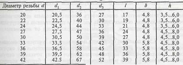
slotted nut 5 and lock washer 6, the inner petal of which fits into the groove of the shaft, and one of the outer ones is bent into the slot of the nut after it is tightened (Fig. 8.5, V); This is a reliable, but relatively expensive method, which is advisable to use when there are significant axial loads acting towards the nut (sizes of nuts and washers
Table 8.5. End washers (GOST 14734-69).Dimensions in mm
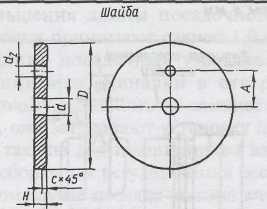
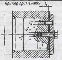
Table 8.6. Round nuts splined (GOST 11871-88).Dimensions in mm
* Preferred sizes.
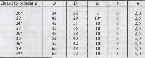
 Note. Thread pitch R d
= 1.5 mm for diameters
Note. Thread pitch R d
= 1.5 mm for diameters= 20...42 mm.Dimensions in mm
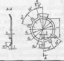
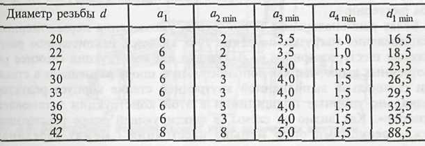
 1.5 mm.Table 8.8. Grooves for the tongue of the lock washer.Dimensions
in mm are given in table. 8.6 and 8.7, the dimensions of the grooves for the exit of the thread-cutting tool are in table. 8.8). Axial fastening of the outer rings of bearings is carried out using the shoulders of the housing (Fig. 8.5, c, d) or glass (Fig. 8.5, G), 2 the dimensions of the shoulders can be taken according to the same recommendations as for the shaft shoulders; spring rings A),(see Fig. 8.5, the design and dimensions of the rings are given in table. 8.9; covers (see Fig. 8.5,
In addition to the methods described above, you can use their design features to fasten bearings. For example, in Fig. 8.5.5 The outer ring of the bearing is made with a groove for a spring thrust flat ring 3. The advantage of this method is that the housing hole does not have a ledge, which complicates its processing. At the same time, the load-bearing capacity of the thrust ring limits the perception of large axial forces. In Fig. 8.5, V The design of a bearing with a shoulder is presented, with which it is kept from moving along the axis.
In Fig. 8.5, d shows how the bearing is secured in the housing using three set screws 8, evenly spaced around the circumference. The tapered ends of the screws act at three points along the circumference on the ring 7. It presses the bearing against the shoulder of the housing. Self-unscrewing screws are secured with a locking ring 9.
When designing supports for bevel gears, which are characterized by the presence of significant axial forces in a constant direction, angular contact roller or ball bearings are widely used (Fig. 8.6). In Fig. 8.6, a B C The bearings are installed in a stretched pattern. For bevel gear supports, this scheme is more preferable, since it ensures the rigidity of the shaft and its supports at the minimum permissible distance l between the bearing centers and increased distance L between support reactions (L> l).
The bearing located closer to the bevel gear is loaded with greater radial force and also absorbs axial force. Therefore, in a number of designs this bearing is chosen as a heavier series (Fig. 8.6, b) or with a larger bore diameter (Fig. 8.6, V). A common disadvantage of the cantilever arrangement of gears (see Fig. 8.6, a B C) is the uneven distribution of load along the length of the gear tooth.
More rational from the point of view of reducing the uneven distribution of load along the length of the tooth is the non-cantilever arrangement of the gear (Fig. 8.6, G). However, this design is more complicated than those discussed above, since additional support is placed in a glass or a specially made inner wall of the gearbox housing. Angular contact bearings in this design are installed “by surprise”. As can be seen from the diagram, in the fixing support the distance L there is less distance between support reactions l between the middles

Rice. 8.6. Designs of bevel gear bearing units
Table 8.9. Spring thrust rings flat internal concentric(GOST 13941-86) and grooves for them.Dimensions in mm

Note. Element sizes T
= 1.9 mm, r  0.2 mm, 20...30 mmi
=
1.7 mm.
0.2 mm, 20...30 mmi
=
1.7 mm.
bearings (L < l), however, the shaft rigidity is quite high due to the presence of a second floating support.
Pump manufacturers use a wide variety of bearing mounting styles in their equipment based on application and load requirements. On small process and general purpose pumps, it is common to see a single row of radial bearings and a double row of thrust bearings.
As machines get larger, speeds are higher, and the radial and axial loads experienced by the shaft and bearing assembly increase, manufacturers often move to larger ball or roller bearings and tandem pairs. angular contact bearings to cope with the increased workload. Of course, when the topic of dual angular contact bearings comes up, the question of how to properly install them also comes up.
"BACK TO BACK"
Many manufacturers install a pair of angular contact bearings on the shaft in a back-to-back configuration. This is where the wider outer races touch each other and the bearings are secured to the shaft using a lock washer and lock nut. This allows the radial and thrust bearing to carry large axial loads in both directions. In a normal installation, when you look at bearings properly mounted on a shaft, you can see a significant number of ball bearings on the outside, and how the wider flange of one bearing contacts the wider flange of another.
"FACE TO FACE"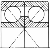
To others, no less effective method is to install the bearings on the shaft face to face. In this case, the inner races are held together by a lock washer and locknut, but the strong load-bearing capacity of this arrangement is not realized until the outer bearing races are secured. This is usually done using a bearing cage, although sometimes springs are used to load the bearing races. With a cage, the procedure may require shims between the cage and the bearing housing to establish preload or internal running clearance. If springs are used, then it is necessary to use those that have the correct spring rate, and not just any springs. Although this setup is more complex, the face-to-face arrangement can eliminate large misalignments between the shaft and housing while providing radial bearings with rigid load-bearing capacity as well as long service life.
"TANDEM"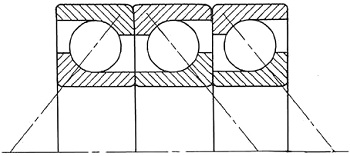
The third method is to mount angular contact bearings on a shaft in tandem. This is when both bearings have the same direction. This arrangement makes for a very loaded thrust bearing arrangement, but it does not carry any radial load and only accepts axial load in one direction. A third angular contact or radial bearing must be added to the set to accommodate radial loads. In combination with a very reliable radial bearing, this allows maximum loads to be transferred in the axial direction.
Information from the equipment manufacturer should always be taken into account to ensure that any composite bearing packages are properly oriented to ensure proper installation. At correct installation, these layouts will ensure a long service life. If done incorrectly, it can lead to breakdown almost immediately.
Once again we were convinced that DPI and KDYD bearings are outright trash! On the electric motor of the spindle drive of a CNC lathe, the bearing worked for only two months! After which it crumbled and jammed. It’s another miracle that the engine didn’t burn out. I am attaching some photos of these “miracle” bearings:
The DPI bearing is pure rubbish! DPI bearing is pure rubbish
People, appreciate your work and don’t allow your bosses to purchase such bearings - the DPI and KDYD bearings WILL not work for long!
I advise you to buy and install either Russian or Ukrainian or SKF. There is no other alternative. Don’t even think about installing parts made in China on the equipment you are repairing.
After we removed this broken bearing, just for fun we tried sawing the bearing housing and balls with an ordinary file. The result is terrible - the file left a chamfer on both the bearing housing and the balls with virtually no tension!
So, draw your own conclusions.
The thrust ball bearing supports only axial loads.
The main feature of the thrust bearing design - which must be remembered during installation - is various internal diameters bearing rings. That is, the thrust bearing has one ring free- it moves freely, with a gap, along the shaft, and the second tight— this ring is installed on the shaft with interference.

The figure shows a diagram of the installation of a thrust ball bearing.
Some explanations for the picture:
- - body - this means the stationary body part of the machine;
- - shaft - a rotating part of the machine that is subject to an axial load.
When installing the thrust bearing main condition things to remember: loose ring is installed in the housing (fixed part), and tight ring- on the shaft. With this installation scheme, the shaft will not rub against the thrust bearing when rotating, since it (the shaft) will rotate in a free ring.
The bearing designation can consist of two designations: main and additional. The main designation encodes the following information: bearing size, type and design. By the way, this is the most important information for us. Additional designation can be located before or after the main one. The additional designation (which comes before the main one) encodes the following information: accuracy class, internal clearance and bearing friction moment. The additional designation (which appears after the main one) codes: bearing material, special technical requirements, type of lubrication, etc. But you should know that if the bearing is produced without special requirements for lubrication, clearance size, etc., then no additional designation is included.
1. Basic symbol.
Symbol for bearings with hole diameters from 10 to 500 mm. For such bearings, the numbers in the main designation are arranged as follows:
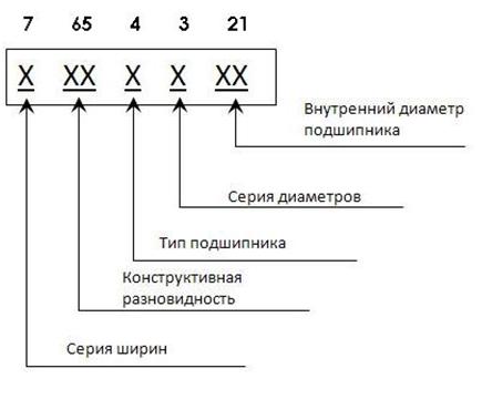
In the basic designation, the order of arrangement and reading of numbers is RIGHT TO LEFT. The numbers can be from two to seven.
Numbers 1 and 2 indicate the inner diameter of the bearing. Moreover, for some diameters there is strict compliance with the symbol:
|
Bearing inner diameter, mm |
Symbol |
Internal diameters from 20 to 495 mm inclusive are designated by the formula: diameter divided by 5.
Here it is necessary to remember that with the same internal diameter, the outer diameter of the bearing and width may be different. This is because the industry produces bearings of various load capacities and designs.
Number 3 denotes a series of diameters.
Number 7 denotes a series of widths.
These series (diameter and width series) define the outer diameter and width of the bearing.
Number 4 indicates the type of bearing.
| Bearing type |
Designation |
| Ball radial | |
| Ball radial spherical | |
| Roller radial with short cylindrical rollers | |
| Roller radial with spherical rollers | |
| Roller radial with long cylindrical or needle rollers | |
| Roller radial with twisted rollers | |
| Angular contact ball | |
| Roller conical | |
| Ball thrust, ball thrust radial | |
| Roller thrust, roller thrust-radial |
Numbers 5 and 6 code the design of the bearing.
Let's consider EXAMPLE symbol millionaire bearing 1180304 . This is a single-row radial ball with a double-sided seal.
04 3 – diameter series; 0 – bearing type; 18 – design; 1 – width series.
Let's consider EXAMPLE bearing symbol 304 . This is a single-row radial ball.
04 – hole diameter (calculate: 04*5 = 20 mm); 3 – diameter series; 0 – bearing type; 00 – design; 0 – width series.
Mounting (or seating) the bearing into the housing. Basically, the sizes of bearings in machines are small, and therefore the installation of bearings is carried out without heating the bearings themselves - that is, in a cold state. Installation occurs according to the following scheme:
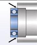
The arrows in the figure indicate the application of force. It is very important. Since the bearing is mounted in a housing, the outer ring absorbs all the force.
In the general case, the same rule applies: the installation force must under no circumstances be transmitted through the rolling elements!
Installation is carried out using pipe cutting. Here it is also worth paying attention that the pipe must be trimmed on a lathe - in general, the edge must be even. No flattened pipes NOT SUITABLE! This can damage the bearing - an uneven pipe can jump off and damage the cage. The diameter of the pipe is selected according to the diameter of the outer ring.
Before starting work, lightly lubricate the outer ring and manually align the bearing in the housing. Now you can begin to install the bearing - first with light blows - here you need to check that there is no distortion, and then push the bearing a little harder until it stops in the housing.
Now, with a slight movement, slide the radial roller bearing onto the cone. The bearing must be secured to the conical neck of the spindle. In most spindle designs this tension will be sufficient. Now you need to measure the gap between the spindle shoulder and the inner race of the bearing. This is done using end measures (tiles). Measurement accuracy +-0.005 mm. Take measurements in at least three places.
- The first and most important condition that must be observed when installing rolling bearings is to ensure the cleanliness of the bearing. That is, if the bearing is new, then it is necessary to remove the preservation grease. If the bearing has already been in operation, then it is necessary to remove the remnants of the former lubricant. It is better to wash the bearings in kerosene, or, if it is impossible to get kerosene, in diesel fuel. As a rule, these liquids can be found in almost any production facility.
- The second is an external examination. The bearings should not have visible damage to the cage or protective washers. It is also necessary to check the ease of rotation and the absence of noise during rotation.
- Third. Inspect the surface on which installation will be carried out - the surface must be clean, smooth, without burrs or nicks.
Installation. Applicable devices.
Important: When installing bearings, the pressing force MUST NEVER BE TRANSMISSED THROUGH THE ROLLING ELEMENTS.
If the bearing is mounted on a shaft, then the force must be transmitted through the inner ring; if the bearing is mounted in a housing, then the force must be transmitted through the outer ring.
A pipe along the diameter of the ring is used as an extension.
It is advisable to create the force when installing the bearing using a press. Of course, it is not always, or rather rarely, when it is possible to assemble a bearing assembly under a press, so this method is used: upsetting with a hammer - through an extension.
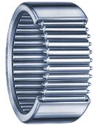 A needle bearing in its design has cylindrical rollers of small diameter, with great attitude roller length to roller diameter. The rollers are located without a separator, one to one. It is this design (without a separator) that is most applicable in the mechanics of machines and equipment.
Needle bearing, compared to conventional roller bearings has the following advantages: higher load capacity with smaller dimensions. Also, needle bearings work very well in rocking motion. Such a rocking motion, for example, occurs in ball screws (ball screws) with small movements.
Series 36000, 46000 and 66000- one-piece.
The axial load capacity of a bearing depends on the contact angle between the rolling element and the raceway. The load carrying capacity of an angular contact ball bearing increases with increasing contact angle.
Angular contact single row bearings series 6000, 36000, 46000, 66000 can take axial load only in one direction, and therefore, to fix the shaft in both, such bearings are usually installed two per shaft or two per support.
Installation diagram two ball angular contact bearings.
This installation scheme is used in almost all milling machine spindles. “A” and “B” - assembly rings - required

to create preload in a set of two bearings (this is necessary for uniform distribution of external loads between the bearings). Preload is achieved by the difference in thickness of rings “A” and “B”. To select the gaps, it is necessary to grind (to reduce the thickness) the outer ring “B”.