How is resistance expressed? Using the Electrical Resistance Converter
The term resistance is in some respects luckier than other physical terms: from early childhood we become familiar with this property of the world around us, mastering our environment, especially when we reach for a toy that we like in the hands of another child, and he resists it. This term is intuitively clear to us, therefore, during school years during physics lessons, getting acquainted with the properties of electricity, the term electrical resistance does not cause us any confusion and its idea is perceived quite easily.
The number of technical implementations of electrical resistance - resistors - produced in the world is incalculable. Suffice it to say that in the most common modern electronic devices - mobile phones, smartphones, tablets and computers - the number of elements can reach hundreds of thousands. According to statistics, resistors make up over 35% of the elements of electronic circuits, and given the scale of production of such devices in the world, we get a mind-boggling figure of tens of trillions of units. Along with other passive radioelements - capacitors and inductors, resistors form the basis of modern civilization, being one of the pillars on which our familiar world rests.

Definition
Electrical resistance- This physical quantity, characterizing certain electrical properties of matter that prevent the free, lossless passage of electric current through it. In terms of electrical engineering, electrical resistance is the characteristic of an electrical circuit as a whole or a section of it to prevent the flow of current and is equal, at constant current, to the ratio of the voltage at the ends of the circuit to the current flowing through it.
Electrical resistance is concerned with the transfer or conversion of electrical energy into other forms of energy. When electrical energy is irreversibly converted into heat, we talk about active resistance. With the reversible conversion of electrical energy into the energy of a magnetic or electric field, if alternating current flows in the circuit, we speak of reactance. If inductance predominates in the circuit, we talk about inductive reactance, if capacitance, we talk about capacitive reactance.
The total resistance (active and reactive) for alternating current circuits is described in terms of impedance, and for alternating electromagnetic fields - by characteristic impedance. Resistance is sometimes not entirely correctly called its technical implementation - a resistor, that is, a radio component designed to introduce active resistance into electrical circuits.
Resistance is indicated by the letter R or r and is considered, within certain limits, a constant value for a given conductor; it can be calculated as

R - resistance, Ohm;
U is the electrical potential difference (voltage) at the ends of the conductor, V;
I is the current strength flowing between the ends of the conductor under the influence of a potential difference, A.
This formula is called Ohm's law, named after the German physicist who discovered this law. An important role in the calculation thermal effect active resistance is played by the law of heat released when an electric current passes through resistance - the Joule-Lenz law:
Q = I 2 ∙ R ∙ t
Q is the amount of heat released over a period of time t, J;
I - current strength, A;
R - resistance, Ohm;
t - current flow time, sec.
Units
The basic unit of measurement of electrical resistance in the SI system is the Ohm and its derivatives: kiloohm (kOhm), megaohm (MOhm). You can find the ratio of SI units of resistance to units of other systems in our unit converter.
Historical reference
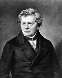
The first researcher of the phenomenon of electrical resistance, and, subsequently, the author of the famous law of the electrical circuit, later named after him, was the outstanding German physicist Georg Simon Ohm. Published in 1827 in one of his papers, Ohm's law played a decisive role in the further study of electrical phenomena. Unfortunately, his contemporaries did not appreciate his research, like many of his other works in the field of physics, and, by order of the Minister of Education, he was even fired from his post as a mathematics teacher in Cologne for publishing the results of his research in newspapers. And only in 1841, after the Royal Society of London awarded him the Copley Medal at a meeting on November 30, 1841, recognition finally came to him. Taking into account the merits of Georg Ohm, in 1881, at the international congress of electricians in Paris, it was decided to name the now generally accepted unit of electrical resistance (“one ohm”) after him.
Physics of phenomena in metals and its application
According to their properties and relative resistance values, all materials are divided into conductors, semiconductors and insulators. A separate class are materials that have zero or close to zero resistance, the so-called superconductors. The most typical representatives of conductors are metals, although their resistance can vary widely, depending on the properties of the crystal lattice.
According to modern concepts, metal atoms combine into a crystal lattice, and the so-called “electron gas” is formed from the valence electrons of the metal atoms.

The relatively low resistance of metals is due precisely to the fact that they contain a large number of current carriers - conduction electrons - belonging to the entire ensemble of atoms of a given metal sample. Arising when an external electric field is applied, the current in the metal represents the ordered movement of electrons. Under the influence of the field, electrons are accelerated and acquire a certain momentum, and then collide with lattice ions. During such collisions, electrons change momentum, partially losing the energy of their movement, which is converted into the internal energy of the crystal lattice, which leads to heating of the conductor when an electric current passes through it. It should be noted that the resistance of a sample of metal or metal alloys of a given composition depends on its geometry, and does not depend on the direction of the applied external electric field.
Further application of an increasingly stronger external electric field leads to an increase in current through the metal and the release of more and more heat, which can ultimately lead to melting of the sample. This property is used in wire fuses for electrical circuits. If the temperature exceeds a certain norm, the wire melts and interrupts the electrical circuit - current can no longer flow through it. The temperature standard is ensured by choosing the material for the wire according to its melting point. An excellent example of what happens to fuses comes from filming a filament burning out in an ordinary incandescent lamp.
The most typical application of electrical resistance is as a fuel element. We use this property when cooking and heating food on electric stoves, baking bread and cakes in electric ovens, as well as when working with electric kettles, coffee makers, washing machines and electric irons. And we don’t think at all that our comfort in Everyday life again, we should be grateful to electrical resistance: whether we turn on a boiler for a shower, or an electric fireplace, or an air conditioner in the mode of heating the air in the room - in all these devices there is always a heating element based on electrical resistance.
In industrial applications, electrical resistance ensures the preparation of semi-finished food products (drying), chemical reactions during optimal temperature for obtaining dosage forms and even in the manufacture of completely prosaic things, such as plastic bags for various purposes, as well as in the production of plastic products (extrusion process).
Physics of phenomena in semiconductors and its application
In semiconductors, unlike metals, the crystal structure is formed due to covalent bonds between the atoms of the semiconductor and therefore, unlike metals, in their pure form they have a significantly higher electrical resistance. Moreover, if they talk about semiconductors, they usually mention not resistance, but their own conductivity.
The introduction of impurities of atoms with a large number of electrons on the outer shell into a semiconductor creates n-type donor conductivity. In this case, the “extra” electrons become the property of the entire ensemble of atoms in a given semiconductor sample and its resistance decreases. Similarly, introducing into a semiconductor impurities of atoms with a smaller number of electrons on the outer shell creates p-type acceptor conductivity. In this case, the “missing” electrons, called “holes,” become the property of the entire ensemble of atoms in a given semiconductor sample and its resistance also decreases.
The most interesting case is the connection of semiconductor regions with various types conductivity, the so-called p-n junction. This transition has the unique property of anisotropy - its resistance depends on the direction of the applied external electric field. When the “blocking” voltage is turned on, the border p-n layer The junction is depleted of conduction carriers and its resistance increases sharply. When an “opening” voltage is applied in the boundary layer, conduction carriers recombine in the boundary layer and the resistance of the pn junction sharply decreases.
The most important elements of electronic equipment - rectifier diodes - are built on this principle. Unfortunately, when a certain current through the pn junction is exceeded, a so-called thermal breakdown occurs, in which both donor and acceptor impurities move through the pn junction, thereby destroying it, and the device fails.
The main conclusion about resistance p-n junctions is that their resistance depends on the direction of the applied electric field and is nonlinear, that is, it does not obey Ohm’s law.
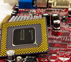
The processes occurring in MOS transistors (Metal-Oxide-Semiconductor) are of a slightly different nature. In them, the source-drain channel resistance is controlled by electric field corresponding polarity for p- and n-type channels created by the gate. MOSFETs are used almost exclusively in the on-off switch mode and make up the vast majority of electronic components in modern digital technology.
Regardless of their design, all transistors in their physical essence are, within certain limits, inertia-free controlled electrical resistances.

Physics of phenomena in gases and its application
In their normal state, gases are excellent dielectrics because they have a very small number of charge carriers - positive ions and electrons. This property of gases is used in contact switches, overhead power lines and air capacitors, since air is a mixture of gases and its electrical resistance is very high.
Since the gas has ionic-electronic conductivity, when an external electric field is applied, the resistance of the gases initially slowly drops due to ionization of everything more molecules. With a further increase in the external field voltage, a glow discharge occurs and the resistance changes to a steeper voltage dependence. This property of gases was previously used in gas-filled lamps - stabistors - to stabilize direct voltage over a wide range of currents. With a further increase in the applied voltage, the discharge in the gas turns into a corona discharge with a further decrease in resistance, and then in the spark discharge - a small lightning appears, and the gas resistance in the lightning channel drops to a minimum.

The main component of the Terra-P radiometer-dosimeter is a Geiger-Muller counter. Its operation is based on the impact ionization of the gas contained in it when hit by a gamma quantum, as a result of which its resistance sharply decreases, which is recorded.
The property of gases to glow when current flows through them in a glow discharge mode is used for the design of neon advertisements, alternating field indications and in sodium lamps. The same property, only when mercury vapor glows in the ultraviolet part of the spectrum, ensures the operation of energy-saving lamps. In them, the luminous flux of the visible spectrum is obtained as a result of the conversion of ultraviolet radiation by a fluorescent phosphor with which the lamp bulbs are coated. The resistance of gases, just like in semiconductors, has a nonlinear dependence on the applied external field and also does not obey Ohm’s law.
Physics of phenomena in electrolytes and its application
The resistance of conducting liquids - electrolytes - is determined by the presence and concentration of ions of different signs - atoms or molecules that have lost or gained electrons. Such ions, when there is a lack of electrons, are called cations; when there is an excess of electrons, they are called anions. When an external electric field is applied (electrodes with a potential difference are placed in the electrolyte), cations and anions begin to move; the physics of the process consists of discharging or charging ions at the appropriate electrode. In this case, at the anode, the anions give up excess electrons, and at the cathode, the cations receive the missing ones.
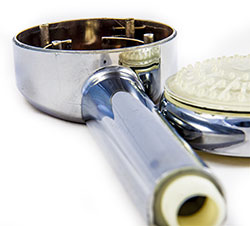
A significant difference between electrolytes and metals, semiconductors and gases is the movement of substances in electrolytes. This property is widely used in modern technology and medicine - from purifying metals from impurities (refining) to introducing medicines into a diseased area (electrophoresis). The sparkling plumbing of our baths and kitchens comes from electroplating processes such as nickel and chrome plating. It is unnecessary to remember that the quality of the coating is achieved precisely by controlling the resistance of the solution and its temperature, as well as many other parameters of the metal deposition process.
Since the human body, from a physical point of view, is an electrolyte, knowledge of the human body’s resistance to the flow of electric current plays an essential role in relation to safety issues. Although the typical value of skin resistance is about 50 kOhm (weak electrolyte), it can vary depending on the individual's psycho-emotional state and conditions environment, as well as the area of skin contact with the electrical conductor. Under stress and anxiety or when in uncomfortable conditions, it can decrease significantly, so for safety calculations of human resistance, a value of 1 kOhm is adopted.
It is curious that based on measuring the resistance of various areas of human skin, the method of operation of the polygraph is based - a “lie detector”, which, along with the assessment of many physiological parameters, determines, in particular, the deviation of resistance from current values when asking the subject “uncomfortable” questions. True, this method is of limited applicability: it gives inadequate results when applied to people with unstable psyches, to specially trained agents, or to people with abnormally high skin resistance.
Within certain limits, Ohm's law is applicable to the current in electrolytes; however, when the external applied electric field exceeds certain values characteristic of a given electrolyte, its resistance is also nonlinear.
Physics of phenomena in dielectrics and its application
The resistance of dielectrics is very high, and this quality is widely used in physics and technology when used as insulators. An ideal dielectric is a vacuum and, it would seem, what kind of resistance in a vacuum can we talk about? However, thanks to one of Albert Einstein’s works on the work function of electrons from metals, which was undeservedly ignored by journalists, in contrast to his articles on the theory of relativity, humanity gained access to the technical implementation of a huge class of electronic devices that marked the dawn of radio electronics, and to this day they work properly serving people.

According to Einstein, any conducting material is surrounded by a cloud of electrons, and these electrons, when an external electric field is applied, form an electron beam. Vacuum two-electrode devices have different resistance when changing the polarity of the applied voltage. Previously, they were used to rectify alternating current. Three or more electrode tubes were used to amplify the signals. Now they are being replaced by more energy-efficient transistors.
However, there remains an area of application where devices based on an electron beam are absolutely irreplaceable - these are X-ray tubes, magnetrons used in radar stations and other electric vacuum devices. Engineers to this day peer into the screens of oscilloscopes with cathode ray tubes, determining the nature of the physical processes taking place, doctors cannot do without X-rays, and we all use microwave ovens every day, which contain microwave emitters - magnetrons.
Since the nature of conductivity in a vacuum is only electronic in nature, the resistance of most electric vacuum devices obeys Ohm's law.
Resistors: their purpose, application and measurement
A resistor is an electronic device needed in all electronic circuits. According to statistics, 35% of any radio circuit consists of resistors. Of course, you can try to come up with a circuit without resistors, but these will only be mind games. Practical electrical and electronic circuits without resistors are unthinkable. From the point of view of an electrical engineer, any device that has resistance can be called a resistor, regardless of its internal structure and method of manufacture. A striking example of this is the story of the crash of the airship “Italy” of the polar explorer Nobile. The expedition's radio operator managed to repair the radio station and send a distress signal, replacing the broken resistor with a pencil lead, which ultimately saved the expedition.

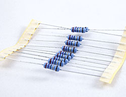
Resistors are elements of electronic equipment and can be used as discrete components or components integrated circuits. Discrete resistors are classified by purpose, type of current-voltage characteristic, method of protection and installation method, nature of resistance changes, manufacturing technologies and dissipated thermal energy. The resistor designation in the circuits is shown in the figure below:
![]()
Resistors can be connected in series or in parallel. When resistors are connected in series, the total resistance of the circuit is equal to the sum of the resistances of all resistors:
R = R 1 + R 2 + … + R n
When resistors are connected in parallel, their total circuit resistance is equal to
R = R 1 ∙ R 2 ∙ … ∙ R n /(R 1 + R 2 + … + R n)
According to their purpose, resistors are divided into:
- general purpose resistors;
- resistors for special purposes.
According to the nature of the change in resistance, resistors are divided into:
By installation method:
- for printed circuit installation;
- for wall-mounted installation;
- for microcircuits and micromodules.
According to the type of current-voltage characteristic:
Color coding of resistors
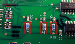
Depending on the dimensions and purpose of the resistors, digital symbolic markings or markings with colored stripes for surface-mounted or printed-circuit mounted resistors are used to indicate their ratings. The symbol in the marking can play the role of a comma in the denomination designation: the symbols R and E are used to denote Ohm, the symbol K is used for kiloohms, and the symbol M is used for megaohms. For example: 3R3 means a nominal value of 3.3 Ohms, 33E = 33 Ohms, 4K7 = 4.7 kOhm, M56 = 560 kOhm, 1M0 = 1.0 Mohm.
The most universal and practical method for determining the value of a resistor and its serviceability is to directly measure its resistance with a measuring device. However, when measuring directly into a circuit, be aware that the circuit's power must be turned off and that the measurement will be inaccurate.
As already noted, the current strength in the circuit depends not only on the voltage at the ends of the section, but also on the properties of the conductor included in the circuit. The dependence of the current on the properties of the conductors is explained by the fact that different conductors have different electrical resistance.
Electrical resistance R is a physical scalar quantity characterizing the property of a conductor to reduce the speed of the ordered movement of free charge carriers in the conductor. Resistance is symbolized by the letter R. The SI unit of resistance of a conductor is the ohm (Ω).
1 Ohm is the resistance of such a conductor, the current in which is 1 A at a voltage of 1 V.
Other units are also used: kiloohm (kOhm), megaohm (MOhm), milliohm (mOhm): 1 kOhm = 10 3 Ohm; 1 MOhm = 10 6 Ohm; 1 mOhm = 10 -3 Ohm.
The physical quantity G, the reciprocal of resistance, is called electrical conductivity
The SI unit of electrical conductivity is the Siemens: 1 cm is the conductivity of a conductor with a resistance of 1 ohm.
A conductor contains not only free charged particles - electrons, but also neutral particles and bound charges. All of them participate in chaotic thermal motion, equally probable in any direction. When the electric field is turned on, under the influence of electric forces, the directed ordered movement of free charges will prevail, which should move with acceleration and their speed should increase over time. But in conductors, free charges move at a certain constant average speed. Consequently, the conductor resists the ordered movement of free charges, part of the energy of this movement is transferred to the conductor, as a result of which its internal energy increases. Due to the movement of free charges, even the ideal crystal lattice of a conductor is distorted; the energy of the ordered movement of free charges is dissipated on the distortions of the crystal structure. A conductor resists the passage of electric current.
The resistance of a conductor depends on the material from which it is made, the length of the conductor, and the cross-sectional area. To check this dependence, you can use the same electrical circuit as for checking Ohm’s law (Fig. 2), including in the section of the MN circuit cylindrical conductors of different sizes, made of the same material, as well as from different materials.
The results of the experiment showed that the resistance of the conductor is directly proportional to the length l of the conductor, inversely proportional to the area S of its cross section and depends on the type of substance from which the conductor is made:
where is the resistivity of the conductor.
A scalar physical quantity numerically equal to the resistance of a homogeneous cylindrical conductor made of a given substance and having a length of 1 m and a cross-sectional area of 1 m 2, or the resistance of a cube with an edge of 1 m. The SI unit of resistivity is the ohm-meter (Ohm m) .
The resistivity of a metal conductor depends on
- concentration of free electrons in a conductor;
- the intensity of scattering of free electrons on ions of the crystal lattice performing thermal vibrations;
- intensity of scattering of free electrons on defects and impurities of the crystal structure.
Silver and copper have the lowest resistivity. The resistivity of the alloy of nickel, iron, chromium and manganese - "nichrome" - is very high. The resistivity of metal crystals largely depends on the presence of impurities in them. For example, the introduction of 1% manganese impurity increases the resistivity of copper three times.
It's time to find out what resistance is. Now imagine an ordinary crystal lattice. So... The closer the crystals are located to each other, the more charges will be retained in them. So, speaking in simple language- the greater the resistance of the metal. By the way, the resistance of any ordinary metal can be temporarily increased by heating it. “Why?”, ask. Yes, because when heated, metal atoms begin to vibrate intensely near their position fixed by bonds. Therefore, moving charges will more often collide with atoms, and therefore more often and more linger in the nodes of the crystal lattice. Figure 1 shows a visual assembly diagram, so to speak, for the “uninitiated,” where you can immediately see how to measure the voltage across the resistance. In exactly the same way, you can measure the voltage on a light bulb. By the way, if, as can be seen from the figure, our battery has a voltage of, say, 15V (Volt), and the resistance is such that 10V “settles” on it, then the remaining 5V will go to the light bulb.
This is what Ohm's law looks like for a closed circuit.
Without going into details, this law says that the voltage of the power source is equal to the sum of the voltage drops in all its sections. Those. in our case, 15V = 10V + 5V. But... if you delve a little into the details, you need to know that what we called the battery voltage is nothing more than its value when a consumer is connected (in our case, this is a light bulb + resistance). If you disconnect the light bulb with the resistance and measure the voltage value on the battery, it will turn out to be slightly more than 15V. It will be tension idle move and it is “called” the EMF of the battery - electromotive force. In reality the circuit will work as shown in Fig. 2. In reality, a battery can be imagined as some other battery with a voltage of, say, 16V, which has its own internal resistance Rin. The value of this resistance is very small and is determined by the technological features of manufacturing. It can be seen from the figure that when a load is connected, part of the battery voltage will “settle” on its internal resistance and its output will no longer be 16V, but 15V, i.e. 1B will be “absorbed” by its internal resistance. Ohm’s law for a closed circuit also applies here. The sum of the voltages in all sections of the circuit will be equal to the emf of the battery. 16V = 1V + 10V + 5V. The unit of resistance is a value called Ohm. It was named after the German physicist Georg Simon Ohm, who was involved in this work. 1 Ohm is equal to the electrical resistance of a conductor (it could, for example, be a light bulb) between the ends of which a voltage of 1 volt occurs at a direct current of 1 ampere. To determine the resistance of the lamp, it is necessary to measure the voltage on it and measure the current in the circuit (see Fig. 5). And then divide the resulting voltage value by the current value (R=U/I). Resistances in electrical circuits can be connected in series (the end of the first with the beginning of the second - in in this case they can be designated arbitrarily) and in parallel (beginning with the beginning, end with the end - and in this case they can be designated arbitrarily). Let's consider both cases using the example of light bulbs - after all, their filaments are made of tungsten, i.e. represent resistance. The case of a serial connection is shown in Fig. 3.
The result is a garland known to everyone (and, therefore, we will consider it understandable). With such a connection, the current I will be the same everywhere, regardless of whether these are identical lamps with the same voltage or different ones. We must immediately make a reservation that lamps on which:
- the same voltage and current are indicated (like light bulbs from a flashlight);
- The same voltage and power are indicated (similar to lighting lamps).
In this case, the voltage U of the power source “spreads” over all lamps, i.e. U = U1 + U2 + U3. Moreover, if the lamps are the same, the voltage on all of them will be the same. If the lamps are not the same, then depending on the resistance of each specific lamp. In the first case, the voltage across each lamp can be easily calculated by dividing the source voltage by the total number of lamps. In the second case, you need to delve into the calculations. We will consider all this in the tasks of this section. So, we found out that when connecting conductors (in this case, lamps) in series, the voltage U at the ends of the entire circuit is equal to the sum of the voltages of the conductors (lamps) connected in series - U = U1 + U2 + U3. According to Omadl's law of the circuit section: U1 = I*R1, U2 = I*R2, U3 = I*R3, U = I*R where R1 is the resistance of the filament of the first lamp (conductor), R2 - the second and R3 - the third, R - impedance of all lamps. Replacing the value of U with I*R, U1 with I*R1, U2 with I*R2, U3 with I*R3 in the expression “U = U1 + U2 +U”, we get I*R = I*(R1+R2+R3 ). Hence R = R1+R2+R3. Conclusion: when conductors are connected in series, their total resistance is equal to the sum of the resistances of all conductors. Let's conclude: sequential connection is used for several consumers (for example, New Year's garland lamps) with a supply voltage lower than the source voltage.
The case of parallel connection of conductors is shown in Fig. 4.
When conductors are connected in parallel, their beginnings and ends have common connection points to the source. In this case, the voltage on all lamps (conductors) is the same, regardless of which of them and what voltage they are designed for, since they are directly connected to the source. Naturally, if the lamp is at a lower voltage than the voltage source, it will burn out. But the current I will be equal to the sum of the currents in all lamps, i.e. I = I1 + I2 + I3. And the lamps can be of different power - each will take the current for which it is designed. This can be understood if, instead of a source, we imagine a socket with a voltage of 220V, and instead of lamps, we imagine, for example, an iron, a table lamp and a phone charger connected to it. The resistance of each device in such a circuit is determined by dividing its voltage by the current it consumes... again, according to Ohm's law for a section of the circuit, i.e.
Let us immediately state the fact that there is a quantity that is the reciprocal of resistance and it is called conductivity. It is designated Y. In the SI system it is designated as Cm (Siemens). The inverse of resistance means that
Without going into mathematical conclusions, we will immediately say that when connecting conductors in parallel (be it lamps, irons, microwaves or televisions), the reciprocal of the total resistance is equal to the sum of the reciprocals of the resistances of all parallel-connected conductors, i.e.
Considering that
Sometimes in problems they write Y = Y1 + Y2 + Y3. It is the same. There is also a more convenient formula for finding the total resistance of two parallel-connected resistances. It looks like this:
Let us conclude: the parallel switching method is used to connect lighting lamps and household electrical appliances to the electrical network.
As we found out, collisions of free electrons in conductors with atoms of the crystal lattice inhibit their forward motion... This is opposition to the directional movement of free electrons, i.e. direct current, constitutes the physical essence of conductor resistance. The mechanism of resistance to direct current in electrolytes and gases is similar. The conductive properties of a material determine its volumetric resistivity ρv, equal to the resistance between opposite sides cube with an edge of 1 m, made of this material. The reciprocal of volume resistivity is called volume conductivity and is equal to γ = 1/ρv. The unit of volumetric resistance is 1 Ohm*m, and the unit of volumetric conductivity is 1S/m. The resistance of a conductor to direct current depends on temperature. In the general case, a rather complex dependence is observed. But when the temperature changes within a relatively narrow range (about 200°C), it can be expressed by the formula:
where R2 and R1 are resistances at temperatures T1 and T2, respectively; α is the temperature coefficient of resistance, equal to the relative change in resistance when the temperature changes by 1°C.
Important Concepts
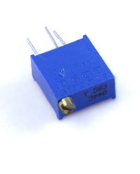
An electrical device that has resistance and is used to limit current is called a resistor. An adjustable resistor (i.e., it is possible to change its resistance) is called a rheostat.
Resistive elements are idealized models of resistors and any other electrical devices or parts thereof that resist direct current, regardless of the physical nature of this phenomenon. They are used in drawing up equivalent circuits and calculating their modes. When idealizing, currents through the insulating coatings of resistors, frames of wire rheostats, etc. are neglected.
A linear resistive element is an equivalent circuit for any part of an electrical device in which the current is proportional to the voltage. Its parameter is resistance R = const. R = const means that the resistance value is unchanged (const means constant).
If the dependence of current on voltage is nonlinear, then the equivalent circuit contains a nonlinear resistive element, which is specified by the nonlinear I-V characteristic (volt-ampere characteristic) I(U) - read as “And from Y”. Figure 5 shows the current-voltage characteristics of linear (line a) and nonlinear (line b) resistive elements, as well as their designations on equivalent circuits.
Among other indicators characterizing an electrical circuit or conductor, it is worth highlighting electrical resistance. It determines the ability of the atoms of a material to prevent the directed passage of electrons. Help in determining this value can be provided by both a specialized device - an ohmmeter, and mathematical calculations based on knowledge of the relationships between quantities and the physical properties of the material. The indicator is measured in Ohms (Ohm), designated by the symbol R.
Ohm's law - a mathematical approach to determining resistance
The relationship established by Georg Ohm defines the relationship between voltage, current, resistance, based on the mathematical relationship of the concepts. The validity of the linear relationship - R = U/I (the ratio of voltage to current) - is not noted in all cases.
Unit [R] = B/A = Ohm. 1 Ohm is the resistance of a material through which a current of 1 ampere flows at a voltage of 1 volt.
Empirical formula for calculating resistance
Objective data on the conductivity of a material follows from its physical characteristics, which determine both its own properties and its response to external influences. Based on this, conductivity depends on:
- Size.
- Geometry.
- Temperatures.
Atoms of the conductive material collide with the directed electrons, preventing them from moving forward. At a high concentration of the latter, the atoms are not able to resist them and the conductivity turns out to be high. Large resistance values are typical for dielectrics, which have virtually zero conductivity.
One of the defining characteristics of each conductor is its resistivity - ρ. It determines the dependence of resistance on the conductor material and external influences. This is a fixed (within one material) value that represents the conductor data of the following dimensions - length 1 m (ℓ), cross-sectional area 1 sq.m. Therefore, the relationship between these quantities is expressed by the relation: R = ρ* ℓ/S:
- The conductivity of a material decreases as its length increases.
- An increase in the cross-sectional area of the conductor entails a decrease in its resistance. This pattern is due to a decrease in the electron density, and, consequently, the contact of material particles with them becomes less frequent.
- An increase in the temperature of the material stimulates an increase in resistance, while a drop in temperature entails its decrease.
It is advisable to calculate the cross-sectional area according to the formula S = πd 2 / 4. A tape measure will help in determining the length.

Relationship with power (P)
Based on the formula of Ohm's law, U = I*R and P = I*U. Therefore, P = I 2 *R and P = U 2 /R.
Knowing the magnitude of the current and power, the resistance can be determined as: R = P/I 2.
Knowing the voltage and power, the resistance can be easily calculated using the formula: R = U 2 /P. 
The resistance of the material and the values of other related characteristics can be obtained using special measuring instruments or based on established mathematical laws.
Let's say right away that we'll talk about resistance measurement electric current. What is it, and how is resistance measured?
Three whales
Where does this resistance even come from? All materials in nature, from the point of view of electrical conductivity, are divided into 3 categories - insulators, semiconductors, and conductors. The former do not conduct electric current at all (for example, glass, plastic, air), the latter pass current only under certain conditions (silicon, germanium), and all modern electronics are built on their basis. But we are interested in the latter – the familiar guides. Ordinary copper wire, the wire that connects your computer to an outlet - all these are conductors.
How can conductors resist electric current? The fact is that an ideal conductor does not exist in nature. In any, even the “cleanest” conductor, there is always some part of impurities that resist electrons moving in the body of the conductor. The collision of electrons with these impurities causes heating, and sometimes (if the flux density is too high, i.e. too much current) and destruction of the conductor (the action of heating elements and fuses is based on this).
A little math
How is the resistance of a conductor, or rather, an electrical circuit, measured? The unit of measurement of this quantity is named after the physicist Georg Simon Ohm. Yes, the same Om whose Law we all studied in school. In the technical literature it is designated by the letter “omega”. The resistance itself is written in calculations as “R” (U – voltage, I – current, P – power, etc.). What does this value mean? Let's look at an example. According to the same Ohm's law, if our conductor has a resistance of 1 Ohm, applying a voltage of 220 volts to its ends, we will get a current (current = voltage divided by resistance) of 220 amperes. By multiplying the current by the voltage, we find out the power: 220 volts * 220 amperes = 48,400 watts, or 48 kilowatts. This is VERY high power that no household wiring can withstand. In fact, such a current will be a short circuit current. This shows how important it is to know the circuit resistance accurately before applying voltage! Fortunately, it is not so difficult to find out, and it is not even necessary to carry out any calculations. There are special measuring instruments - ohmmeters, which show the value of direct current resistance. A type of megohmmeter is designed for measuring large resistance values, and is used mainly for testing insulation. Nowadays it is difficult to find ohmmeters as separate devices. For the most part, they are part of combined instruments - avometers, or multimeters, which are sold in every Chinese goods stall.
So, good luck with your measurements!