Physical foundations of mechanics
Since the time of Galileo's experiments on the Leaning Tower of Pisa, it has been known that all bodies fall in the field of gravity with the same acceleration g.
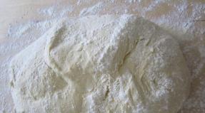
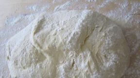
However, everyday practice indicates something else: a light feather falls slower than a heavy metal ball. The reason for this is also clear - air resistance.
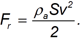
Equations of motion. If we limit ourselves to the case of translational motion of non-rotating bodies in a stationary medium with resistance, then the resistance force will be directed against the speed. In vector form it can be written as
where is the absolute value of this force, a is the module of the body’s velocity. Taking into account the resistance of the medium changes the form of the equations of motion of a body thrown at an angle to the horizon:
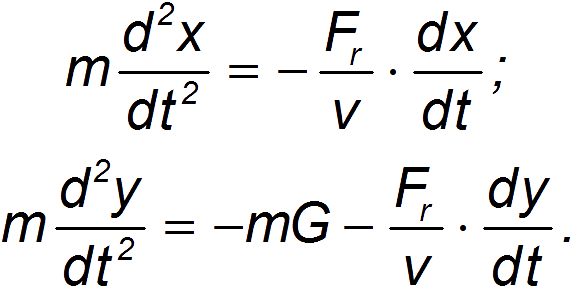
The above equations also take into account the buoyant force of Archimedes acting on the body: acceleration of free fall g replaced by a smaller value
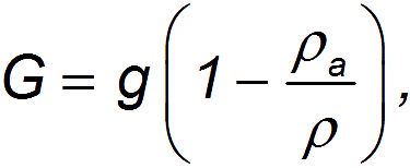
where is the density of the medium (for air = 1.29 kg/m3), and is the average density of the body.
Indeed, the weight of a body in a medium decreases by the amount of the Archimedes buoyancy force
Expressing the volume of a body through its average density

we arrive at the expression

In the presence of air resistance, the speed of a falling body cannot increase indefinitely. In the limit, it tends to a certain steady value, which depends on the characteristics of the body. If the body has reached a steady falling speed, then from the equations of motion it follows that the resistance force is equal to the weight of the body (taking into account the Archimedean force):

The resistance force, as we will soon see, is a function of the rate of fall. Therefore, the resulting expression for the resistance force is an equation for determining the steady-state rate of fall. It is clear that in the presence of a medium, the energy of the body is partially spent on overcoming its resistance.
Reynolds number. Of course, it is impossible to even begin to solve the equations of motion of a body in a liquid while we know nothing about the modulus of the drag force. The magnitude of this force significantly depends on the nature of the counter flow of gas (or liquid) around the body. At low speeds this flow is laminar(that is, layered). It can be imagined as the relative movement of layers of a medium that do not mix with each other.
Laminar fluid flow is demonstrated by the experiment shown in Fig. 13.
As already noted in Chapter 9.3, with the relative movement of layers of liquid or gas between these layers, movement resistance forces arise, which are called forces of internal friction. These forces are due to the special property of fluid bodies - viscosity, which is characterized numerically viscosity coefficient. Let's give characteristic values for various substances: for air ( = 1.8 10 -5 Pa s), water ( = 10 –3 Pa s), glycerin ( = 0.85 Pa s). Equivalent designation of units in which the viscosity coefficient is measured: Pa s = kg m –1 s –1.
There are always adhesion forces between a moving body and the medium, so that immediately near the surface of the body, a layer of gas (liquid) is completely delayed, as if “sticking” to it. It rubs against the next layer, which is slightly behind the body. That, in turn, experiences frictional force from an even more distant layer, etc. Layers very far from the body can be considered at rest. Theoretical calculation of internal friction for the movement of a ball with a diameter D leads to Stokes formula:
Substituting the Stokes formula into the expression for the resistance force during steady motion, we find the expression for the steady velocity of the ball falling in the medium:
It can be seen that the lighter the body, the lower the speed of its fall in the atmosphere. The resulting equation explains to us why a fluff falls slower than a steel ball.
When solving real problems, for example, calculating the steady fall speed of a parachutist during a long jump, one should not forget that the friction force is proportional to the speed of the body only for a relatively slow laminar counter flow of air. As the speed of a body increases, air vortices arise around it, the layers mix, and the movement at some point becomes turbulent, and the resistance force increases sharply. Internal friction (viscosity) ceases to play any significant role.
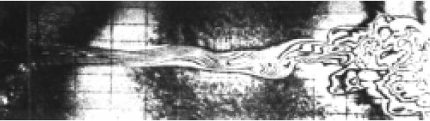
Rice. 9.15 Photograph of a liquid jet during the transition from laminar to turbulent flow (Reynolds number Re=250)
The emergence of a resistance force can then be imagined as follows. Let the body pass a path in the environment. With a resistance force, work is spent on this
If the cross-sectional area of the body is equal to , then the body will “collide” with particles occupying the volume. The total mass of particles in this volume is equal to · Let us imagine that these particles are completely entrained by the body, acquiring speed . Then their kinetic energy becomes equal

This energy did not appear out of nowhere: it was created due to the work of external forces to overcome the force of resistance. That is, A=K, where
We see that now the resistance force depends more strongly on the speed of movement, becoming proportional to its second power (cf. Stokes' formula). In contrast to the forces of internal friction, it is often called dynamic drag force.
However, the assumption full of enthusiasm particles of the medium by a moving body turns out to be too strong. In reality, any body is somehow flown around by a flow, which reduces the force of resistance. It is customary to use the so-called drag coefficient C, writing the drag force in the form:

For turbulent flow in a certain speed range C does not depend on the speed of movement of the body, but depends on its shape: say, for a disk it is equal to one, and for a ball it is approximately 0.5.
Substituting the formula for the drag force into the expression for the drag force during steady motion, we arrive at a different expression than the previously obtained formula for the steady velocity of the ball falling (at C = 0,5):

Applying the formula found to the movement of a parachutist weighing 100 kg with a transverse parachute size of 10 m, we find

which corresponds to the landing speed when jumping without a parachute from a height of 2 m. It can be seen that the formula corresponding to a turbulent air flow is more suitable for describing the movement of a parachutist.
The expression for the drag force with the drag coefficient is convenient to use over the entire speed range. Since the drag regime changes at low speeds, the drag coefficient in the region of laminar flow and in the transition region to turbulent flow will depend on the speed of the body. However, direct dependence C from is impossible, since the drag coefficient is dimensionless. This means that it can only be a function of some dimensionless combination involving speed. This combination, which plays an important role in hydro- and aerodynamics, is called Reynolds number(see topic 1.3).
The Reynolds number is a parameter that describes the change in regime during the transition from laminar to turbulent flow. Such a parameter can be the ratio of the drag force to the internal friction force. Substituting the expression for the cross-sectional area of the ball into the formula for the drag force, we are convinced that the magnitude of the drag force, up to numerical factors that are now unimportant, is determined by the expression

and the magnitude of the internal friction force is expressed by
The ratio of these two expressions is the Reynolds number:

If we are not talking about the movement of the ball, then under D refers to the characteristic size of the system (say, the diameter of a pipe in a problem about fluid flow). By the very meaning of the Reynolds number, it is clear that at its small values, internal friction forces dominate: the viscosity is high and we are dealing with a laminar flow. At large Reynolds numbers, on the contrary, dynamic drag forces dominate and the flow becomes turbulent.
The Reynolds number is of great importance when simulating real processes on smaller (laboratory) scales. If for two currents different sizes Reynolds numbers are the same, then such flows are similar, and the phenomena arising in them can be obtained from each other by simply changing the scale of measurement of coordinates and velocities. Therefore, for example, using a model of an airplane or car in a wind tunnel, it is possible to predict and study the processes that will arise during real operation.
Resistance coefficient. So, the drag coefficient in the formula for the drag force depends on the Reynolds number:

This dependence has a complex character, shown (for a ball) in Fig. 9.16. Theoretically, it is difficult to obtain this curve, and usually the dependences measured experimentally for a given body are used. However, its qualitative interpretation is possible.
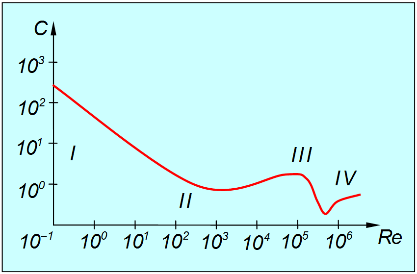
Rice. 9.16. Dependence of the drag coefficient on the Reynolds number (Roman numerals indicate the range of values of Re; which correspond to different modes of air flow)
Region I. Here the Reynolds number is very small (< 1) и течение потока ламинарно. Экспериментальная кривая описывается в этой области функцией

By substituting this value into the previously found formula for the drag force and using the expression for the Reynolds number, we arrive at the Stokes formula. In this region, as already mentioned, resistance arises due to the viscosity of the medium.
Region II. Here the Reynolds number lies in the range 1< < 2·10 4 . Данная область соответствует переходу от ламинарного к турбулентному течению. Экспериментальные данные свидетельствуют, что при увеличении числа Рейнольдса достигается некоторое его критическое значение, после которого стационарное ламинарное течение становится неустойчивым. Разумеется, это критическое значение не универсально и различается для different types currents. But its characteristic value is on the order of several tens.
At only slightly larger critical values, unsteady periodic flow motion appears, characterized by a certain frequency. With further increase, the periodic motion becomes more complex, and more and more frequencies appear in it. These frequencies correspond to periodic movements (vortices), the spatial scales of which become increasingly smaller. The movement becomes more complex and confusing - turbulence develops. In this region, the drag coefficient continues to fall with increasing , but more slowly. The minimum is reached at = (4–5) 10 3, after which WITH increases slightly.
Region III. This region corresponds to a developed turbulent flow around the ball, and we have already encountered this regime above. The typical values of the Reynolds number here lie in the range 2·10 4< < 2·10 5 .
When a body moves, it leaves behind a turbulent wake, beyond which the flow is laminar. A turbulent wake vortex is easy to observe, for example, at the stern of a ship. Part of the surface of the body is directly adjacent to the region of the turbulent wake, and its front part is adjacent to the region of laminar flow. The boundary between them on the surface of the body is called the separation line. Physical cause The occurrence of the resistance force is the pressure difference on the front and rear surfaces of the body. It turns out that the position of the separation line is determined by the properties of the boundary layer and does not depend on the Reynolds number. Therefore, the resistance coefficient is approximately constant in this mode.
Region IV. However, such a regime of flow around a body cannot be maintained up to arbitrarily large values. At some point, the forward laminar boundary layer becomes turbulent, which pushes the separation line back. The turbulent wake behind the body narrows, which leads to a sharp (4–5 times) drop in the resistance of the medium. This phenomenon is called crisis of resistance, occurs in a narrow range of values = (2–2.5)·10 5 . Strictly speaking, the above theoretical considerations may change when taking into account the compressibility of the medium (air, in our case). However, this will manifest itself, as we have already discussed, at object speeds comparable to the speed of sound.
Additional Information
http://ilib.mirror1.mccme.ru/djvu/bib-kvant/kvant_70.djvu - Stasenko A.L. Physics of flight, Kvant Library, issue 70 pp. 17–28 - aerodynamic forces acting on the wing.
http://d.theupload.info/down/8osiz73swyx22j1icv3641f3xxe8rtdp/butikov_e_i__kondratev_a_s__fizika_dlja_uglublennogo_izuchen.djvu - E.I. Butikov, A.S.Kondratiev, Tutorial; Book 1, Mechanics, Fizmatlit, 2001 - Chapter V - movement of liquids and gases.
List of additional links
http://kvant.mirror1.mccme.ru/pdf/1998/02/kv0298fizfak.pdf - Kvant magazine - mathematical pendulum on inclined surfaces (P. Hadji, A. Mikhailenko).
http://kvant.mirror1.mccme.ru/1971/06/strannyj_mayatnik.htm - “Kvant” magazine - a mathematical pendulum with a movable suspension point (N. Mints);
http://edu.ioffe.ru/register/?doc=physica/lect4.ch1.tex - The lecture discusses harmonic oscillations, the phase portrait of a pendulum, adiabatic invariants.
http://www.plib.ru/library/book/9969.html - E.I. Butikov, A.S. Kondratiev, Textbook; Book 1, Mechanics, Fizmatlit, 2001 - pp. 279–295 (§§ 42,43) - damped oscillations during dry friction and natural oscillations in various physical systems are described.
http://mechanics.h1.ru/ - Mechanics at school, definitions of basic physical quantities, problem solving.
http://edu.ioffe.ru/register/?doc=mgivanov - A course of lectures on mechanics for a physics and technology school (M.G. Ivanov).
http://ilib.mirror1.mccme.ru/djvu/bib-kvant/kvant63.djvu - Aslamazov L.G., Varlamov A.A. Amazing physics, Quantum Library, issue 63, chapter 2 - simple physics of complex phenomena.
http://schools.keldysh.ru/sch1275/kross/ - Physical crosswords.
http://www.newsland.ru/News/Detail/id/211926/22 - The possibility of creating an audio and optical “invisibility cap” is being discussed.
http://ilib.mirror1.mccme.ru/djvu/bib-kvant/kvant_40.djvu - Khilkevich S.S., Physics around us, Kvant library, issue 40, chapter 1, § 5 - how vibration and what happens when you shake a bucket of potatoes.
One of the manifestations of mutual gravitational force is gravity, i.e. the force of attraction of bodies towards the Earth. If only the force of gravity acts on a body, then it undergoes free fall. Consequently, free fall is the fall of bodies in airless space under the influence of gravity towards the Earth, starting from a state of rest.
Galileo first studied this phenomenon, but due to the lack of air pumps, he could not conduct experiments in airless space, so Galileo carried out experiments in air. Discarding all secondary phenomena encountered when bodies move in the air, Galileo discovered the laws of free fall of bodies. (1590)
- 1st law. Free fall is a rectilinear uniformly accelerated motion.
- 2nd law. The acceleration of gravity in a given place on the Earth is the same for all bodies; its average value is 9.8 m/s.
The dependencies between the kinematic characteristics of free fall are obtained from formulas for uniformly accelerated motion, if in these formulas we put a = g. For v0 = 0 V = gt, H = gt2\2, v = √2gH.
In practice, air always resists the movement of a falling body, and for a given body, the greater the speed of fall, the greater the air resistance. Consequently, as the speed of falling increases, air resistance increases, the acceleration of the body decreases, and when the air resistance becomes equal to the force of gravity, the acceleration of a freely falling body becomes zero. In the future, the movement of the body will be a uniform movement.
The actual movement of bodies in the earth's atmosphere occurs along a ballistic trajectory, which differs significantly from the parabolic one due to air resistance. For example, if you fire a bullet from a rifle at a speed of 830 m/s at an angle α = 45° to the horizon and use a movie camera to record the actual trajectory of the tracer bullet and the location of its impact, then the flight range will be approximately 3.5 km. And if you calculate it using the formula, it will be 68.9 km. The difference is huge!
Air resistance depends on four factors: 1) SIZE of the moving object. A large object will obviously receive more resistance than a small one. 2) SHAPE of a moving body. A flat plate of a certain area will provide much greater wind resistance than a streamlined body (droplet shape) having the same cross-sectional area for the same wind, actually 25 times greater! The round object is somewhere in the middle. (This is the reason why the bodies of all cars, airplanes and paragliders are rounded or teardrop-shaped whenever possible: it reduces air resistance and allows you to move faster with less effort on the engine, and therefore less fuel). 3) AIR DENSITY. We already know that one cubic meter weighs about 1.3 kg at sea level, and the higher you go, the less dense the air becomes. This difference can play some practical role when taking off only from a very high altitude. 4) SPEED. Each of the three factors considered so far makes a proportional contribution to air drag: if you double one of them, the drag also doubles; if you reduce either of them by half, the resistance drops by half.
AIR RESISTANCE is equal to HALF THE DENSITY OF THE AIR multiplied by the DRAG COEFFICIENT multiplied by the SECTIONAL AREA and multiplied by the SQUARE OF VELOCITY.
Let's introduce the following symbols: D - air resistance; p - air density; A - cross-sectional area; cd - resistance coefficient; υ - air speed.
Now we have: D = 1/2 x р x cd x A x υ 2
When a body falls under real conditions, the acceleration of the body will not be equal to the acceleration of gravity. In this case, Newton’s 2nd law will take the form ma = mg – Fresist –Farch
Farkh. =ρqV , since the air density is low, it can be neglected, then ma = mg – ηυ
Let's analyze this expression. It is known that a drag force acts on a body moving in the air. It is almost obvious that this force depends on the speed of movement and the size of the body, for example, the cross-sectional area S, and this dependence is of the type “the larger υ and S, the larger F.” You can also clarify the type of this dependence based on considerations of dimensions (units of measurement). Indeed, force is measured in newtons ([F] = N), and N = kg m/s2. It can be seen that the second squared is included in the denominator. From here it is immediately clear that the force must be proportional to the square of the body’s speed ([υ2] = m2/s2) and density ([ρ] = kg/m3) - of course, the medium in which the body moves. So,
And to emphasize that this force is directed against the velocity vector.
We have already learned a lot, but that's not all. Surely the drag force (aerodynamic force) also depends on the shape of the body - it is no coincidence that aircraft are made “well streamlined”. To take into account this expected dependence, it is possible to introduce a dimensionless factor into the relation (proportionality) obtained above, which will not violate the equality of dimensions in both parts of this relation, but will turn it into equality:
Let's imagine a ball moving in the air, for example, a pellet, flying out horizontally with an initial speed - If there were no air resistance, then at a distance x in time the pellet would move vertically downwards by. But due to the action of the drag force (directed against the velocity vector), the time of flight of the pellet to the vertical plane x will be greater than t0. Consequently, the force of gravity will act on the pellet longer, so that it will fall below y0.
And in general, the pellet will move along a different curve, which is no longer a parabola (it is called a ballistic trajectory).
In the presence of an atmosphere, falling bodies, in addition to gravity, are affected by the forces of viscous friction with the air. To a rough approximation, at low speeds, the force of viscous friction can be considered proportional to the speed of movement. In this case, the equation of motion of the body (Newton’s second law) has the form ma = mg – η υ
The force of viscous friction acting on spherical bodies moving at low speeds is approximately proportional to their cross-sectional area, i.e. squared body radius: F = -η υ= - const R2 υ
The mass of a spherical body of constant density is proportional to its volume, i.e. cube of radius m = ρ V = ρ 4/3π R3
The equation is written taking into account the downward direction of the OY axis, where η is the air resistance coefficient. This value depends on the state of the environment and body parameters (body weight, size and shape). For a spherical body, according to the Stokes formula η =6(m(r where m is the mass of the body, r is the radius of the body, ( is the air viscosity coefficient.
Consider, for example, the fall of balls from different materials. Let's take two balls of the same diameter, plastic and iron. Let us assume for clarity that the density of iron is 10 times greater than the density of plastic, so the iron ball will have a mass 10 times greater, and accordingly its inertia will be 10 times higher, i.e. under the same force it will accelerate 10 times slower.
In a vacuum, only the force of gravity acts on the balls; on an iron ball it is 10 times greater than on a plastic one; accordingly, they will accelerate with the same acceleration (10 times the greater force of gravity compensates for the 10 times greater inertia of the iron ball). With the same acceleration, both balls will travel the same distance in the same time, i.e. in other words, they will fall simultaneously.
In the air: the force of aerodynamic drag and the Archimedean force are added to the action of gravity. Both of these forces are directed upward, against the action of gravity, and both depend only on the size and speed of movement of the balls (do not depend on their mass) and at equal speeds of movement are equal for both balls.
T.o. the resultant of the three forces acting on the iron ball will no longer be 10 times greater than the similar resultant of the wooden one, but more than 10, and the inertia of the iron ball remains greater than the inertia of the wooden one by the same 10 times. Accordingly, the acceleration of the iron ball will be greater than that of the plastic one, and he will fall earlier.
Instructions
Find the force of resistance to motion that acts on a body moving uniformly in a straight line. To do this, use a dynamometer or other method to measure the force that must be applied to the body so that it moves evenly and in a straight line. According to Newton's third law, it will be numerically equal to the resistance force of the body's motion.
Determine the force of resistance to the movement of a body that moves along a horizontal surface. In this case, the friction force is directly proportional to the reaction force of the support, which, in turn, is equal to the force of gravity acting on the body. Therefore, the force of resistance to movement in this case or the friction force Ftr is equal to the product of body mass m, which is measured by scales in kilograms, by the acceleration of free fall g≈9.8 m/s² and the proportionality coefficient μ, Ftr = μ∙m∙g. The number μ is called the coefficient of friction and depends on the surfaces that come into contact during movement. For example, for friction between steel and wood, this coefficient is 0.5.
Calculate the force of resistance to the movement of a body moving along an inclined plane. In addition to the friction coefficient μ, body mass m and gravitational acceleration g, it depends on the angle of inclination of the plane to the horizon α. To find the force of resistance to movement in this case, you need to find the products of the friction coefficient, body mass, acceleration of gravity and the cosine of the angle at which the plane is inclined to the horizon Ftr=μ∙m∙g∙cos(α).
When a body moves in the air at low speeds, the resistance force Fс is directly proportional to the speed of the body v, Fc=α∙v. Coefficient α depends on the properties of the body and the viscosity of the medium and is calculated separately. When moving at high speeds, for example, when a body falls from a significant height or a car moves, the resistance force is directly proportional to the square of the speed Fc=β∙v². The coefficient β is additionally calculated for high speeds.
For determining strength resistance air create conditions under which the body begins to move uniformly and linearly under the influence of gravity. Calculate the value of gravity, it will be equal to the force of air resistance. If a body moves in the air, picking up speed, its resistance force is found using Newton's laws, and the air resistance force can also be found from the law of conservation of mechanical energy and special aerodynamic formulas.
You will need
- rangefinder, scales, speedometer or radar, ruler, stopwatch.
Instructions
Before measuring resistance For a used resistor, be sure to unsolder it from the old board or block. Otherwise, it may be bypassed by other parts of the circuit, and you will get incorrect readings from it. resistance.
Video on the topic
To find electrical resistance conductor, use the appropriate formulas. The resistance of a circuit section is found according to Ohm's law. If the material and geometric dimensions of the conductor are known, its resistance can be calculated using a special formula.

You will need
- - tester;
- - caliper;
- - ruler.
Instructions
Remember what the concept of resistor means. IN in this case A resistor should be understood as any conductor or element of an electrical circuit that has active resistive resistance. Now it is important to ask how a change in resistance value affects the current value and what it depends on. The essence of the resistance phenomenon is that the atoms of the resistor substance form a kind of barrier to the passage of electrical charges. The higher the resistance of a substance, the more densely the atoms are located in the lattice of the resistive substance. This pattern explains Ohm’s law for a section of a chain. As you know, Ohm's law for a section of a circuit is as follows: the current strength in a section of a circuit is directly proportional to the voltage in the section and inversely proportional to the resistance of the section of the circuit itself.
Draw on a piece of paper a graph of the dependence of the current on the voltage across the resistor, as well as on its resistance, based on Ohm’s law. You will get a graph of a hyperbola in the first case and a graph of a straight line in the second case. Thus, the greater the voltage across the resistor and the lower the resistance, the greater the current strength. Moreover, the dependence on resistance is more pronounced here, because it has the appearance of a hyperbole.
Note that the resistor's resistance also changes as its temperature changes. If you heat a resistive element and observe the change in current strength, you will notice how the current decreases as the temperature increases. This pattern is explained by the fact that as the temperature increases, the vibrations of atoms in the nodes of the crystal lattice of the resistor increase, thus reducing the free space for the passage of charged particles. Another reason that reduces the current strength in this case is the fact that as the temperature of the substance increases, the chaotic movement of particles, including charged ones, increases. Thus, the movement of free particles in the resistor becomes more chaotic than directed, which affects the decrease in current strength.
Video on the topic
Introduction
The development of laws (functions) of air resistance has a long history. Outstanding scientists and artillerymen were engaged in this, and as a result of numerous range shootings, the dependences of the drag coefficient on the Mach number were obtained, which strongly depend on the characteristics of the oncoming air flow around the projectile, i.e. mainly on the configuration of the head part. However, even with this dependence, calculating the trajectory parameters of an artillery shell has always been an extremely difficult task, especially when factors such as the curvature of the surface and the rotation of the Earth are taken into account.
To calculate the trajectory of a projectile, it is necessary to numerically integrate a system of differential equations of external ballistics using the extremely labor-intensive finite difference method, and at the beginning of the last century, computers had only adding machines and abacus at their disposal. The new type of gun required its own tables; they had to be compiled over the years, having previously conducted range firing to determine the parameters of the accepted law of air resistance (mainly the projectile shape coefficient). It is known that the Germans carried out the first external ballistic calculations, considering the air density constant and equal to the average value within the trajectory altitude.
It is for the rapid compilation of ballistic tables commissioned by the US Army at the Ballistic Research Laboratory. in 1946, the first Eniak computer was created ( ENIAC - Electronic Number Integrator And Computer- Electronic digital integrator and computer). Calculations on the Eniak were carried out in the decimal system, and changing the program required thousands of switches to be set to a certain position and hundreds of cables to be connected, so on average it took two days of painstaking manual work to prepare the machine to calculate one table.
Thus, accelerating the process of calculating trajectory parameters has always been an urgent task in cannon and then rocket artillery. To obtain adequate results, an appropriate mathematical description of the resistance law is necessary. The most popular in this sense long time was Siacci's law (function) in the form of an empirical formula, the important advantage of which is its continuous dependence on the speed of the projectile. However, the formula was derived in relation to outdated blunt-headed projectiles used as reference ones. With the advent of modern long-range projectiles, new laws of air resistance were created. However, unlike the Siacci formula, they are given in discrete (most often in tabular) form.
The most common law of air resistance in Russia (formerly in the USSR), used in calculating the trajectories of artillery shells, is the law of 1943. However, there is still no representation of this law in the form of a continuous dependence on the speed of the projectile, which makes it difficult to carry out calculations on a computer. This paper proposes a way to reduce Siacci's law to the 1943 law using the corresponding matching coefficient in the form of a function that continuously depends on the projectile speed. It is shown that the discrepancy between the calculation results using the proposed approximation and the tabulated data does not exceed what is acceptable from a practical point of view.
The application of the technique is illustrated with a specific example.
1 General formula for air resistance force
Figure 1 shows a diagram of the forces applied to the projectile along the trajectory: - gravity; - resultant of aerodynamic forces, i.e. air resistance force. It is applied at the center of pressure WITH, not coinciding with the center of mass O. The distance between these points is determined by Gobar's formula. In the figure, δ is the angle of attack, i.e. the angle between the projectile axis and the tangent to the trajectory at a given point (the projectile velocity vector lies on the tangent); - the angle between the velocity vector and the horizon. If the force is transferred to the center of mass ABOUT and simultaneously apply a balancing force () to this point, then a pair of forces arises that creates an overturning moment (this is taken into account when studying the motion of a projectile as a rigid body). The force applied at the center of mass is decomposed into two components: - the drag force (it lies on the tangent to the trajectory and is directed in the direction opposite to the velocity vector) and - the lift force. In the following, we consider a simplified diagram of the application of these forces, assuming and considering that the force is directed along the axis of the projectile; in this case and .
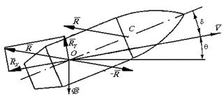
Figure 1 - Forces applied to the projectile along the trajectory
The structure of the fundamental expression for the air resistance force is obtained using the theory of similarity and dimensions, which underlies physical modeling methods:
|
 ,
,where is the air density; - midsection area of the projectile ( d- caliber); - speed pressure; - drag coefficient; - Mach number; a- speed of sound at a given point in the trajectory; - Reynolds number; - kinematic viscosity coefficient.
The dependence is determined experimentally for projectiles of a standard (“reference”) shape . The similarity of the processes of air flow around projectiles is most often not ensured due to the difference in the configuration of the head part, and in order to be able to use the available experimental data, a projectile shape coefficient is introduced
 ,
,
taking into account the incompleteness of similarity conditions. This coefficient is relatively weakly dependent on the projectile speed, and it is convenient to use as a coefficient for coordinating the calculation for determining the firing range with experience. In this case, both the shape of the projectile and other physical factors affecting the movement of the projectile are taken into account.
Transforming formula (1), we obtain an expression for the “acceleration of air resistance”
Where q- mass of the projectile. Next, introduce the function
Where y- height; - air density on the Earth's surface at the point of the shot. In addition, to obtain values of the corresponding quantities that are more convenient for practical calculations, a multiplier is introduced
where kg/m 3 is the air density for normal artillery conditions. Then (2), taking into account (1), will have the form
This expression includes the ballistic coefficient
 ..
..
It is usually accepted that, i.e.
 .
.
Here the relative mass coefficient (“lateral load”) is introduced, where d- in decimeters. It can be seen that the ballistic coefficient (and, consequently, the force of air resistance) changes in inverse proportion to the caliber.
is called the law of air resistance, which is often called dependence. By omitting the constant factor in (4), we can write the proportional relation
 .
.
As is known, the speed of sound
where is the adiabatic index for air, usually taken equal to 1.4; R- universal gas constant; ![]() - “virtual” temperature, taking into account air humidity; T- absolute temperature; e- water vapor pressure; h- humid air pressure/
- “virtual” temperature, taking into account air humidity; T- absolute temperature; e- water vapor pressure; h- humid air pressure/
The standard laws of air resistance are reduced to the speed of sound in normal conditions ![]() m/s, so the argument is converted:
m/s, so the argument is converted:
 .
.
 -
-
so-called virtual speed. Thus,
Respectively,
|
 .
.
The dependency is usually specified by:
Having carried out rather cumbersome calculations associated with the integration of the corresponding expressions, we obtain
|
2 Laws of air resistance
L. Euler, when solving the problem of projectile flight, used the function ![]() , established by Newton and used mainly for subsonic speeds. One of the first was the power function of Maievsky-Za-bud-skogo
, established by Newton and used mainly for subsonic speeds. One of the first was the power function of Maievsky-Za-bud-skogo
![]()
When compiling this formula, the old-shaped projectile with a short head, long cylindrical and waist parts was taken as a reference. The coefficients were chosen so that at the boundaries of the regions the resistance values were the same, but at the same time corner points appeared on the graph, as a result of which the derivatives of the resistance with respect to speed suffered finite discontinuities at these points. In addition, when calculating a trajectory, it is inconvenient to divide it into a number of sections according to speed. Currently, this law is not used in practice.
Based on the works of Maievsky-Zabudsky and experiments late XIX century, Italian ballistician Francesco Siacci proposed a new air resistance function that bears his name (1888). Siacci also accepted the old shape as a reference projectile, but smoothed out the corner points on the graph. Siacci’s great merit is the empirical approximation of the law of air resistance in the form he proposed (5):
This law has been tested many times in practice and is widely used in calculating trajectories, with the appropriate value of the shape coefficient. At low speeds, Siacci's law is close to quadratic, and at high speeds it is close to linear.
With the development of artillery, the modern long-range projectile with an elongated head and a relatively short tail becomes the main one. Experiments to create a new function were carried out after the First World War in a number of countries, for example, in 1921-1923. in France (Garnier and Dupuis laws).
In our country, the law of air resistance was created in 1930. On its basis, tables of external ballistics of the ANII were compiled, but it turned out that this law gives inaccurate results when calculating a trajectory with high initial velocities; In addition, the shape coefficient of modern projectiles in relation to the function of 1930 fluctuates noticeably at different speeds.
3 Law 1943
Before the Great Patriotic War In the USSR, work began on establishing a new function of air resistance based on processing the results of firing with modern long-range projectiles. These works were completed in 1943, the new function was called the law of the Artillery Academy. F.E. Dzerzhinsky, or simply the law of 1943. At the same time. An error in the Siacci function was discovered, which manifests itself at a projectile speed of more than 1410 m/s. The 1943 law was adopted in our country as the main one. All ballistic calculations are carried out in relation to this function, although, due to the presence of tables, the 1930 and Siacci functions are also used.
A complete table of the 1943 law is contained in the book; in an abbreviated form it is given in, along with the laws of Siacci and 1930. In the 1943 function, it is specified within a limited range (), divided into sections:

There is the following description of the 1943 law:
Table 1 - Transition factor
Speed, m/s | M | Transition factor |
0…150 | 0…0,44 | 0,61 |
150…250 | 0,44…0,733 | 0,58 |
250…300 | 0.733…0,880 | 0,48 |
300…341 | 0,880…1,0 | 0.60 |
341…400 | 1,0…1,173 | 0,57 |
400…500 | 1,173…1,466 | 0,50 |
500…700 | 1,466…2,053 | 0,45 |
700…1000 | 2,053…2,932 | 0,48 |
It can be seen that the transition factor noticeably depends on the speed, so averaging it within one or another speed range can lead to calculation errors in another range.
The shape coefficients for modern projectiles (PF) in relation to the 1943 law vary within the limits, and in relation to the Siacci function.
Thus, known methods descriptions of the 1943 law define it discretely (by points or by subranges); the law does not have an empirical description in the form of a single continuous function of speed within the entire range of changes in the Mach number, similar to Siacci’s law. The discrete nature of the description of the 1943 law is inconvenient when calculating trajectories on a computer, and therefore they are trying to express it through Siacci’s law, introducing a corrective transition factor, however, this factor is also specified discretely. Therefore, in practice they often prefer to use Siacci’s law, but at a certain shape coefficient i, determined by known shooting conditions.
4 Approximation of the 1943 law
One can propose this method of correcting Siacci's law and bringing it to the law of 1943. Having determined the (discrete) dependence of the shape factor on speed from the tabular data, then approximate it as a kind of continuous function of speed and then recalculate as follows:
The results of implementing this idea in the MathCAD package environment are presented in Figure 2, where 1 - ; 2 - tabular law of 1943; 3 - matching function ![]() ; 4- approximation of the matching function; 5 -
; 4- approximation of the matching function; 5 - ![]() .
.
The matching function is approximated by a 3rd order polynomial:
whose coefficients are determined using the MathCAD function linfit, relating to a linear combination of approximating formulas:
; ![]() ;
; ![]() ;
; ![]() .
.

Figure 2 - Approximation of the 1943 law:
From Figure 2 it is clear that the approximating curve ![]() in general, it is quite close to the tabular dependence, with the exception of the section in the maximum area, however, this should not lead to a significant error, especially at high projectile speeds ().
in general, it is quite close to the tabular dependence, with the exception of the section in the maximum area, however, this should not lead to a significant error, especially at high projectile speeds ().
Thus, we accept the following empirical description of the 1943 law:
|
Table 2 compares the data presented in the work with those obtained using the proposed approximation: 1 - tabular values; 2 - calculation using this method; 3 - deviation, %.
Table 2 - Comparison of approximating and tabulated values
M | |||
0,158 | 0,1 576 | 0,25 |
|
0,158 | 0,15 77 | 0,19 |
|
0,157 | 0.15 70 | ||
0,160 | 0.1 57 | 1,88 |
|
0,335 | 0. 3454 | 3,10 |
|
0,385 | 0.3 87 | 0,52 |
|
0,378 | 0.37 6 | 1,31 |
|
0,351 | 0.3 556 | 1 ,3 1 |
|
0,332 | 0.3 344 | 0,72 |
|
0,316 | 0.3 161 | 0 ,03 |
|
0,287 | 0.28 42 | 0,98 |
|
0,270 | 0.26 68 | 1 , 18 |
|
0,261 | 0.25 93 | 0 , 65 |
|
0,260 | 0.2 575 | 0,96 |
It can be seen that the difference between the calculation results based on approximation and the tabulated values is quite acceptable from a practical point of view.
5 Calculation example
We illustrate the application of the proposed approximation using the example of calculating the parameters of the projectile trajectory of the battleship Bismarck, which was carried out by the author during mathematical modeling of the shelling of the English battlecruiser Hood on May 24, 1941. Detailed description The “duel” of two outstanding ships is given in.
In the work we read: “...shape coefficient i should be considered as a parameter that allows the results of theoretical calculations to be consistent with experimental data. For example, let an experimental firing range be found on the basis of firing projectiles of a certain type at fixed values of initial velocity and throwing angle X....By size X, and the projectile shape coefficient can be determined i. If the trajectory is calculated using the coefficient satisfying the expression ![]() with the same values of and , then we obtain a firing range that coincides with the experimental one. This method is used to determine the form factor when compiling firing tables for a specific gun.”
with the same values of and , then we obtain a firing range that coincides with the experimental one. This method is used to determine the form factor when compiling firing tables for a specific gun.”
The corresponding calculations are carried out using a well-known system of equations describing the motion of a projectile as a material point:
where is the angle of inclination of the tangent to the trajectory (velocity vector) relative to the horizon.
This is how the coefficient was determined i for Bismarck shells. The battleship was equipped with eight 380-mm guns (two in each of the four turrets) 38cm/52 SK C/34. It is known that maximum range 35,550 m is achieved with the mass of the projectile 800 kg, muzzle velocity 820 m/s and elevation angle. By the selection method, using the appropriate program for the numerical solution of system (9), it was determined and .
The paper presents trajectory parameters when firing at different elevation angles; Table 3 compares these data with the calculation results obtained using Siacci's law at (in the denominator). The discrepancy between these data amounts to units and fractions of a percent. Siacci's law was used because the calculations made by the Germans could only be obtained using this law. This is confirmed by information in the article, which presents the results of calculations of the external ballistics of the Bismarck, carried out in 1939-1940. during the completion of the battleship at the Blom and Voss shipyard. These results are also presented in graphical form on the website of the battle cruiser Hood.
Table 3 - Comparison of data with calculation results using the proposed method
Elevation angle hail | Range shooting, m | Angle of incidence projectile, hail | Flight time, s | Fall speed projectile, m/s |
|
5000 / 4 860 | 2,4 / - 2,38 | 6,5 / 6,29 | 727 / 729,4 |
||
10000 / 9 900 | 5,8 / - 5,75 | 13,9 / 13.68 | 641 / 644,2 |
||
15000 / 14 880 | 10,4 / - 10,27 | 22,3 / 22,03 | 568 / 572,7 |
||
12,1 | 20000 / 20 040 | 16,4 / -16,37 | 32,0 /31,92 | 511 / 516,2 |
|
16,8 | 25000 / 25 090 | 23,8 / - 23,62 | 43,0 / 42,92 | 473 / 481,3 |
|
22,4 | 30000 / 30 120 | 31,9 / - 31,62 | 55,5 / 55,34 | 457 / 467,4 |
|
29,1 | 0,97 | 527 ,7 | 13 ,9 | 27 ,89 |
|
Data [14] |
The discrepancy between the required elevation angle values, as well as the final trajectory parameters, is small. The results of calculations using Siacci’s law are closest to the German data, which indicates the use of this particular law. The form factor for the 1943 law is slightly less than unity, i.e. Bismarck shells had a “longer range” shape compared to the standard shells used to obtain the 1943 law.
Conclusion
The main results of the work are as follows.
1) The possibility of bringing the law of air resistance of 1943, adopted in Russia as the main one when calculating the trajectories of artillery shells, to Siacci’s law is considered. The advantage of the latter is the continuous dependence on the speed of the projectile, however, this law was obtained for outdated, blunt-headed projectiles and cannot be directly used in calculating modern ones, i.e. long-range projectiles.
2) The correction factor is proposed in the form of an analytical approximation of a sequence of discrete matching coefficients, which is a continuous function of the Mach number. Thanks to the use of the proposed approximation, the calculation of trajectory parameters on a computer is simplified.
3) It is shown that the difference between the calculation results using the proposed method and the tabulated values does not exceed what is acceptable from a practical point of view.
4) An example of using the proposed approximation is given.
Bibliography
1. Efremov A.K. Reconstruction of the design of an ultra-long-range gun - the “Paris Cannon” // Izvestia RARAN. 2010. Issue 3(65). pp. 105-116.
2. Dmitrievsky A.A., Lysenko L.N. External ballistics: textbook. for universities. 4th ed. M.: Mechanical Engineering, 2005. 608 p.
3. Ventzel D.A., Okunev B.N., Shapiro Ya.M. External ballistics. Part I. L.: Art. acad. them. F.E.Dzerzhinsky, 1933.
4. Shapiro Ya.M. External ballistics. M.: Oborongiz, 1946.
5. Gantmakher F.R., Levin M.A. The theory of flight of unguided rockets. M.: Fizmatgiz, 1959. 360 p.
6. Pravdin V.M., Shanin A.P. Ballistics of unguided aircraft. Snezhinsk: Publishing house RFNC-VNIITF, 1999. 496 p.
7. Efremov A.K. Autonomous information and control systems. In 4 vols. T. 4 / Ed. A.B. Borzova. M.: LLC Scientific Research Center "Engineer", LLC "Oniko-M", 2011. 330 p.
8. Müllenheim-Rechberg B.B., background. Battleship "Bismarck": trans. from English / ed. A.K. Efremova. M.: Eksmo, 2006.
9. Ballistics of barrel systems / RARAN; ed. L.N. Lysenko and A.M. Lipanova. M.: Mechanical Engineering, 2006.
10. Campbell J. Naval Weapons of World War Two. London: Conway Maritime Press, 2002.
11. Jurens W.J. The Loss of HMS Hood - a Re-Examination // Warship International. 1987. Vol. 24, no. 2. P. 122-180.
12. Obercommando der Kriegsmarine, Unterlagen und Richtlinien zur Bestimmung der Hauptkampfentfernung und der Geschoswahl. Berlin. 1940.
Georgy Alexandrov
LITERATURE REVIEWWhen falling in the air, a body moves under the influence of two forces: the constant force of gravity, directed vertically downward, and the force of air resistance, increasing as it falls and directed vertically upward. The resultant force of gravity and the force of air resistance is equal to their difference and is directed downward at the beginning of the fall.
The drag force is caused, firstly, by the friction of air on the surface of the body and, secondly, by the change in flow movement caused by the body. In an air flow modified by the presence of a body, the pressure on the front side of the body increases, and on the back side it decreases compared to the pressure in the undisturbed flow. Thus, a pressure difference is created, braking a moving body or dragging a body immersed in a flow. The movement of air behind the body takes on a chaotic vortex character.
It is easy to see that air resistance significantly influences the nature of the fall of bodies. If you simultaneously release a stone and a piece of cotton wool of approximately the same volume from your hands, the stone will fall to the Earth quickly, while the cotton wool will fall much more slowly. If you make a dense ball out of this piece of cotton wool, then the speed of its fall will increase. A similar situation can be observed when two identical sheets of paper fall, one of which is crumpled into a ball - it will fall faster.
In many cases, air resistance has little effect on the fall of bodies and can be neglected. But if the fall occurs from a very high altitude, then air resistance will have a noticeable effect on the fall of even very heavy bodies.
For small solid bodies, air resistance at the Earth's surface is small. But if you observe the fall of light bodies of large volume, you will notice that they move uniformly accelerated and for a very short time. When falling, the speed of such bodies gradually increases, but at the same time the force of air resistance acting on these bodies also increases. This continues until the force of air resistance balances the force of gravity. At this moment, the increase in speed will stop, and the body will fall further at a constant speed, i.e. uniformly. This speed can be called the maximum speed of a falling body.
The value of this speed depends on the size, shape and mass of bodies. Light droplets of water, specks of dust and fluff, reach their maximum speed very quickly, flying a little more than five meters - and with this steady speed they fall further evenly. The speed of raindrops at the Earth's surface is usually 7-8 m/s; the smaller the drop, the lower the speed of its fall; if raindrops fell in airless space, then when falling to the ground from a height of 2 km, they would reach, regardless of their size, a speed of 200 m/s; any other body would reach the same speed when falling from the same height in airless space. At that speed, the impact of raindrops would be quite unpleasant! For a skydiver in a skydive, the maximum speed is approximately 50 m/s, and with the parachute open, the skydiver's maximum speed is reduced to 5-6 m/s.
Difference in top speed different bodies same shape, but of different sizes is explained by the dependence of the resistance of the medium on the size of the body. It turns out that the resistance is approximately proportional to the transverse dimensions of the body. A disk, a ball and a cigar-shaped body of the same cross-section at the same falling speed will experience air resistance forces that are completely different in magnitude: for a disk it will be 25 times, and for a ball it will be 5 times greater than for a cigar-shaped body.
Therefore, various bodies, depending on their purpose, are given the appropriate shape: aerial bombs are given a special streamlined shape, in which air resistance is low; This is done with the goal that the bomb reaches the ground as quickly as possible and better penetrates obstacles (dugout, ship deck, etc.). On the contrary, the skydiver must reach the ground at a low speed. Therefore, the parachute is given a shape in which the air resistance to its movement would be as great as possible. The maximum falling speed of a person with an open parachute is 5-7 m/sec. Achieving maximum speed by a parachutist occurs differently than when the body simply falls. Initially, the parachutist falls with a closed parachute and, due to low air resistance, reaches a speed of tens of meters per second. When the parachute opens, air resistance increases sharply and, many times exceeding the force of gravity, slows the fall to the maximum speed.
Air resistance somewhat changes the nature of movement. When a body moves upward, both the force of gravity and the force of air resistance are directed downward. Therefore, the speed of the body decreases faster than in the absence of air resistance. Therefore, the speed of such a body decreases to zero at a height less than that to which the body would rise in the absence of air resistance. During a subsequent fall, resistance slows down the increase in the body's speed, and therefore the body returns to the Earth not at the same speed with which it was thrown, but at a lower one. Therefore, the time of rising up in real conditions is less than the time of falling.
The influence of air resistance on the nature of the movement of bodies is especially great when high speeds. Thus, a bullet fired from a gun vertically upward at a speed of 600 m/s could reach an altitude of almost 18 kilometers in the absence of air resistance, but in fact it takes off “only” 2-3 km.
D= 1/2(R x CD x A x V 2 )
D- air resistance;
R- (pronounced "ro") - air density;
A- cross-sectional area;
CD- resistance coefficient;
V- air speed.